JJ 12AY7 Preamp Tube Design Tutorial: Build Better Tone
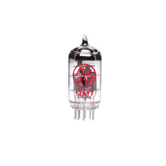
The JJ Electronic 12AY7 is a dual-triode miniature preamp tube pin-compatible with the 12AX7 but with roughly 45% of the voltage gain (mu ≈ 44 vs. 100) and higher transconductance headroom at low plate currents. That lower gain is exactly why it shines in this tutorial: it lets you build a single-ended, Class-A voltage-gain stage with useful headroom, low microphonics, and a forgiving bias window, making it ideal for learning tube design without chasing instability. JJ's current production is consistent and quiet enough for a first build, and the 12AY7's moderate mu keeps the math friendly.
Design requirements: a single triode gain stage, 250 V B+ supply, target midband voltage gain of ~30, output impedance under 50 kΩ, and clean output swing of at least 6 V peak. Input impedance 1 MΩ, and a frequency response of 20 Hz–20 kHz within ±1 dB. We will use one half of the 12AY7, leaving the second section available for a cathode follower or a second stage later.
Step 1 — Choose the operating point. From the 12AY7 datasheet, at Vp = 150 V and Ip = 2 mA, mu ≈ 44 and rp ≈ 22 kΩ. Pick Vp = 150 V, Ip = 2 mA for good linearity and headroom. With B+ = 250 V, the plate resistor RL drops 100 V at 2 mA, so RL = 100 V / 2 mA = 50 kΩ (use 47 kΩ standard).
Step 2 — Set the cathode bias. We want Vgk ≈ −2 V at 2 mA. Rk = 2 V / 2 mA = 1 kΩ. Bypass it with a capacitor to keep AC gain high: choose fc = 5 Hz, Ck = 1/(2π·5·1000) ≈ 32 µF; use 47 µF for margin.
Step 3 — Estimate gain. Av = −mu·(RL ∥ rp)/(rp + RL ∥ rp)... simpler: Av = mu·RL/(RL + rp) = 44·47k/(47k + 22k) ≈ 30. This meets the target. Output impedance ≈ RL ∥ rp ≈ 15 kΩ.
Step 4 — Coupling networks. Input coupling Cin with Rg = 1 MΩ at fc = 5 Hz gives Cin = 1/(2π·5·1M) ≈ 32 nF; use 0.1 µF. Output coupling into a 100 kΩ load: Cout = 1/(2π·5·100k) ≈ 0.32 µF; use 1 µF.
BOM rationale: RL 47 kΩ 1 W metal-film (dissipation ~0.2 W, derate for reliability); Rk 1 kΩ 0.5 W; Rg 1 MΩ 0.25 W; Ck 47 µF/25 V electrolytic (bypass); Cin, Cout 0.1 µF and 1 µF film (low leakage, stable). Use a 9-pin ceramic or bakelite socket with gold-plated contacts. B+ filter: 22 µF reservoir + 10 kΩ/22 µF RC decoupling before the plate resistor to kill ripple. Heater: 6.3 V AC or DC at 0.3 A; DC heaters reduce hum in a first build.
Simulation tips: Model the triode with a Koren or Ayumi model for the 12AY7; run a DC sweep of Vgk to confirm the operating point lands at ~150 V, 2 mA. Then run AC analysis and check gain flatness and −3 dB corners. Perform a transient test with a 1 kHz, 0.2 V peak sine and watch for asymmetric clipping at the output; adjust bias slightly if clipping is uneven. Check input impedance and output loading effects.
Prototype build: Build on a small aluminum chassis or turret board. Keep grid wiring short and shielded, ground the cathode resistor locally, and use a single star ground at the input jack. Bring B+ up slowly with a variac or a series 100 Ω resistor while measuring plate voltage. Verify heater voltage before applying B+.
Testing and verification: Measure DC bias first: Vp ≈ 150 V, Vk ≈ 2 V. Inject a 1 kHz sine at 0.1 V RMS and measure gain; expect ~30 (±10%). Sweep 20 Hz–20 kHz to confirm bandwidth. Check output swing to clipping and THD with a scope or sound-card analyzer; aim for <1% at 2 V RMS output. If gain is low, verify Ck polarity and value; if hum appears, improve heater wiring and ground returns. Optimize by fine-tuning Rk (±10%) for symmetric clipping and by adding a small grid-stopper resistor (1 kΩ) to suppress RF pickup.