MGW100515 DC DC Converter Datasheet Guide: ±15V 10W Explained
The Cosel MGW100515 is a dual-output, isolated DC-DC converter delivering +15 V and −15 V rails at a combined 10 W, and its datasheet rewards careful reading because several specifications interact in ways that are easy to miss. The headline numbers—input range, output voltages, and rated power—are straightforward, but the practical behavior of the part depends on line and load regulation, ripple and noise, isolation voltage, and efficiency curves that vary with input and load conditions. Engineers specifying this module for analog front ends, op-amp rails, or industrial signal conditioning should treat the datasheet as a system-level document rather than a simple parameter table.
Key electrical specifications begin with the input voltage range, which for the MGW series is typically a nominal 24 V DC input with a defined operating window. The input range tells you how much headroom exists for supply sag, battery discharge, or backplane tolerance. Output voltage accuracy is specified at a given load and temperature, usually with a tolerance band around ±15 V; line regulation describes how much the output moves as the input varies across its range, while load regulation describes the change from no load to full load. For a ±15 V rail feeding precision analog circuitry, both matter because any deviation propagates directly into signal offset. Ripple and noise is specified over a bandwidth (often 20 MHz) and should be read alongside the recommended external filtering; the bare module figure is not what your load will see if you add the suggested capacitors. Efficiency, typically quoted at full load and nominal input, determines dissipated power and therefore thermal design. Isolation voltage—often 1.5 kV DC or similar—defines the barrier between input and output and is a safety and noise-immunity parameter, not a continuous working voltage rating for arbitrary transients.
Absolute maximum ratings and derating deserve separate attention. The datasheet lists maximum input voltage, output current per rail, operating and storage temperature, and case or baseplate temperature limits. These are stress limits, not operating points. The 10 W total output power is shared between the two rails, so a load of 500 mA on +15 V consumes 7.5 W and leaves only 2.5 W, roughly 166 mA, for the −15 V rail; asymmetric loading is permitted but must respect the total. Derating curves show how allowable output power or current falls as ambient or case temperature rises, and the relevant temperature is frequently the baseplate or a defined measurement point rather than free-air ambient. Read the derating footnotes to determine which temperature governs, and derate conservatively if the module sits in an enclosure with poor airflow.
Typical application circuits in the datasheet show the input filter, the recommended input capacitor for source impedance and transient suppression, and output capacitors selected for stability and ripple. Many isolated converters require a minimum load on one or both outputs for regulation, and the datasheet will state whether the −15 V rail needs a bleeder resistor when the positive rail is lightly loaded. The application section also illustrates grounding: whether the outputs are floating, referenced to input common, or tied to chassis. For dual supplies, the common node between +15 V and −15 V is usually the analog ground, and the isolation barrier allows that node to sit at a different potential from the input return. Follow the recommended layout for the input loop and keep the output return paths short and symmetric to preserve the dual-rail balance.
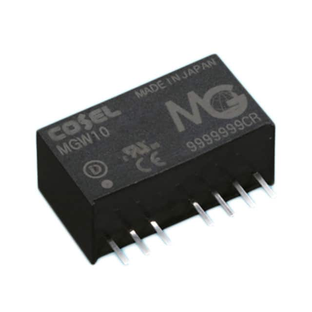
Pin configuration and package details define the mechanical and electrical interface. The datasheet pinout table identifies input positive and negative, output positive, output common, and output negative, along with any trim, remote sense, or on/off control pins if present. Pay attention to pin numbering orientation and the recommended footprint, including keep-out areas and the location of the baseplate or case for thermal contact. The package drawing gives insertion depth for through-hole versions or pad geometry for surface-mount variants, and the datasheet notes the torque or soldering conditions where applicable. Verify the pinout against the physical marking on the module before powering a new design; miswiring the dual output is a common and destructive error.
Thermal management guidance centers on the derating curve and the specified temperature measurement point. The module dissipates roughly the difference between input power and the 10 W output, so at 85 percent efficiency the loss is on the order of 1.8 W. Conduction and convection through the case, plus any baseplate contact with the PCB or heatsink, determine the temperature rise. The datasheet typically specifies a maximum case temperature and may provide thermal resistance figures; use these to estimate junction or component temperatures under worst-case ambient. If the design operates near the derating limit, add copper area or airflow and verify the measurement point in the actual enclosure rather than on an open bench.
Characteristic curves and timing diagrams are where the datasheet becomes predictive. Efficiency versus output current curves show the load range where the converter is most efficient, often around 50 to 80 percent of rated load; the low-load region is where efficiency drops and where minimum-load requirements appear. Ripple versus load and temperature curves reveal whether noise grows at light load. The output voltage versus input voltage curve confirms regulation across the input range. Startup timing diagrams give the rise time, the delay from input application to output regulation, and the behavior of both rails relative to each other—critical if downstream logic or amplifiers require sequencing. Transient response curves show the deviation and recovery time for a step load, which tells you how much bulk capacitance the load needs. Read each curve at the conditions stated in its legend, and interpolate cautiously between plotted points.