N-Type Male Crimp Connector BC-201-400-BK: Reliability Guide
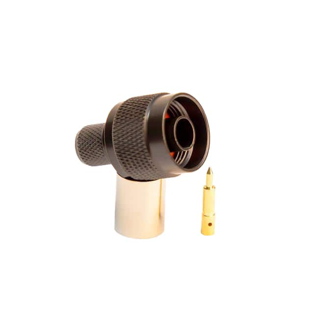
The Big Cat Cables BC-201-400-BK is a 50-ohm N-type male crimp connector with black plating, intended for RG-8/RG-213-class coaxial cable in RF and industrial applications. Because N connectors sit at the boundary between sensitive electronics and the outside world, their reliability is governed as much by mechanical and environmental integrity as by electrical performance. Reliability qualification for this component should reference MIL-STD-348 (interface dimensions), MIL-STD-202 (environmental and mechanical test methods), MIL-STD-1344 (connector test methods), and the IEC 61169-16 series for N-type connectors. Where the end application demands it, test data aligned to EIA-364 is also acceptable. Key qualified parameters include contact resistance (typically below 3 mΩ initially), insulation resistance above 5 GΩ, dielectric withstanding voltage of 1,500 Vrms at sea level, VSWR of 1.3:1 or better to 11 GHz, and RF leakage below −90 dB. Procurement should request the manufacturer's qualification test report and a certificate of conformance referencing these standards; a datasheet alone is insufficient evidence of reliability.
Accelerated life testing for crimp connectors combines thermal cycling, thermal shock, vibration, mechanical mating durability, and salt fog. A representative program might run 500 thermal cycles from −55 °C to +125 °C, 2,000 mating cycles, random vibration per MIL-STD-202 Method 214, and 96 hours of salt fog per Method 101. Results are interpreted as margin statements: post-test contact resistance drift of less than 10 mΩ and VSWR shift under 0.1 indicate a robust design, while any dielectric breakdown or plating corrosion invalidates the lot. Buyers should treat accelerated data as trend evidence, not a warranty — it demonstrates design margin but does not predict field life without correlation to actual service conditions.
FIT-rate calculations for a passive connector are often misapplied. Published FIT figures for connectors generally derive from field return data or MIL-HDBK-217-style part stress models, and a single crimp connector may carry an assumed failure rate on the order of 0.1 to 1 FIT in benign environments, rising sharply with thermal cycling and mating frequency. MTBF for a connector is not a meaningful standalone metric; system MTBF should allocate connector contribution based on mate/unmate count and environment. For procurement, request the supplier's basis of calculation and reject any FIT claim presented without a stated environment, confidence level, and data source.
Environmental stress screening (ESS) and burn-in apply mainly to assembled cable harnesses rather than loose connectors. For incoming lots, a practical screen is 100% visual and dimensional inspection plus sample-based thermal shock (−55/+125 °C, 5 cycles) and insulation resistance testing. Burn-in is not standard for passive connectors and should not be specified unless the connector is part of a powered assembly. If the supplier offers ESS, verify the screening profile and failure-reporting method; screening without a documented failure analysis loop provides little reliability value.
Counterfeit N connectors are common and often exhibit soft brass bodies, thin or missing plating, out-of-tolerance threads, and incorrect dielectric material. Detection methods specific to this component include: verifying the 7/16-20 UNEF thread with a go/no-go gauge; checking center-pin dimensions and captive contact retention; confirming plating thickness by X-ray fluorescence (black plating should be consistent and adherent); weighing the part against a known-good reference; and inspecting crimp ferrules for correct material and wall thickness. Ask for lot traceability, date codes, and factory audit evidence. Suspect parts should be quarantined and tested per AS6081 guidance.
Incoming inspection should combine AQL sampling with critical-parameter 100% checks: interface dimensions, contact retention (minimum 20 N axial force), dielectric integrity, and plating appearance. Retain first-article samples and perform periodic VSWR sweeps on assembled test cables. Document every lot with photographs and measurement records to support future failure investigations.
Storage should be in a dry, temperature-controlled area (15–25 °C, below 60% RH), with connectors kept in sealed bags and original packaging to prevent tarnish and contamination. Avoid handling center pins with bare hands; skin oils degrade plating and insulation. During assembly, use the correct crimp tool and die per the manufacturer's specification, and inspect crimp height and pull strength. End-of-life planning should account for supplier discontinuation risk: qualify a second source, maintain a buffer stock sized to lead time plus qualification duration, and monitor PCN/EOL notices. Because N connectors are mature parts, obsolescence is usually driven by supplier exit rather than technology change, so dual sourcing and documented alternates are the most effective mitigation.