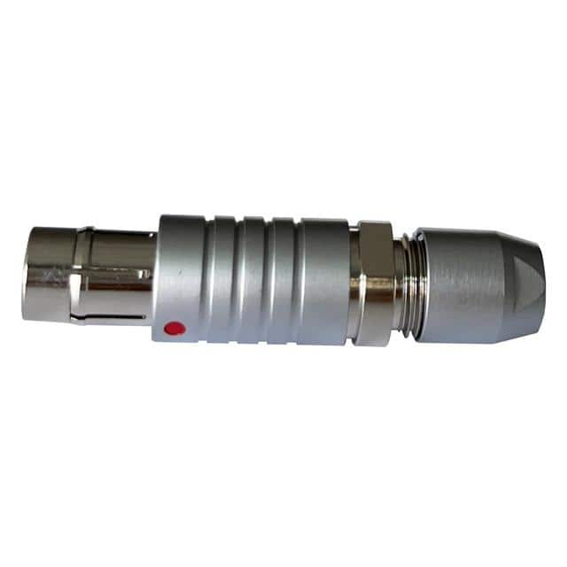
CONN PLUG MALE 3P Gold Solder Cup IP68 Application Guide
The Adam Tech MMI-M0P103S52-IP68 is a 3-position male plug connector with gold-plated solder-cup terminations and an IP68 sealing rating, making it well suited to power, signal, and low-speed data interfaces in harsh or outdoor environments. This application note provides practical guidance for integrating the connector into new designs, with emphasis on reliability, manufacturability, and long-term field performance.
Recommended circuit topologies depend on the intended function. For power delivery, a single-ended topology with a dedicated ground return is strongly preferred. Avoid using the connector for both power and high-impedance analog signals unless the return currents are carefully separated, as shared returns can introduce noise coupling. For sensor or low-speed data links, a differential pair on two of the three contacts with the third used as a shield or ground reference provides the best noise immunity. When the connector is used for a single-ended signal, keep the signal current low and route the return through the nearest available contact rather than relying on chassis ground, which can create ground loops. In all topologies, ensure the connector's voltage and current ratings are derated by at least 30 percent for continuous operation to account for contact heating and IP68 sealing constraints.
Supporting passive selection should focus on transient protection and filtering. Place a TVS diode or transient voltage suppressor across each signal line and return, sized to the maximum expected surge and with a clamping voltage below the absolute maximum rating of downstream circuitry. For power lines, add a resettable fuse or eFuse upstream of the connector. Series ferrite beads or small resistors (10 to 100 ohms) on signal lines help damp high-frequency ringing and limit fault currents. Decoupling capacitors should be placed close to the connector's downstream ICs, not at the connector itself, to avoid creating a low-impedance path for ESD into sensitive nodes. Use X7R or C0G dielectrics rated for at least twice the operating voltage.
PCB layout should keep the connector footprint compact and the solder-cup pads accessible for hand or reflow soldering. Provide generous annular rings and thermal reliefs on the pads to aid solder flow, and avoid placing vias directly under the solder cups where wicking could occur. Route signal traces away from the connector's sealing features and keep a minimum clearance of 0.5 mm between traces and the connector body to prevent solder bridging. For IP68 performance, the PCB-to-connector interface must be mechanically supported; add mounting holes or a bracket so that cable strain is not transferred to the solder joints. Route high-current paths with wide traces and multiple vias, and keep sensitive analog traces on a separate layer with a continuous ground plane beneath them.
EMC and EMI mitigation begins at the connector. The gold-plated contacts provide low contact resistance, but the cable shield, if present, should be terminated to the connector shell or a dedicated ground contact using a 360-degree bond. Add a common-mode choke on differential pairs and a feed-through capacitor or pi-filter on power lines. Keep the connector's ground return path short and direct to the chassis or ground plane. If the enclosure is metallic, ensure a low-impedance bond between the connector shell and the enclosure; if plastic, add a local ground plane and shield can around sensitive circuitry. Test radiated emissions with the cable attached, as the cable often becomes the dominant antenna.
Common design pitfalls include over-tightening the connector during assembly, which can crack the solder joints or damage the seal, and using excessive solder on the cups, which can wick into the contact area and cause intermittent opens. Another frequent error is ignoring the connector's mating cycle rating and using it as a frequently disconnected service port. Avoid routing signals that exceed the connector's rated frequency, and do not assume IP68 protection applies when the mating half is unmated or improperly torqued. Finally, ensure the cable jacket and strain relief are compatible with the connector's sealing gland; mismatched cable diameters are a leading cause of water ingress.
For prototyping, solder a short pigtail to the connector and test continuity and insulation resistance before potting or final assembly. Perform a bench test that includes a 500 V insulation resistance check between adjacent contacts and between contacts and the shell, followed by a functional test at the intended operating voltage and current. Subject the assembly to a thermal cycle from -40 to +85 degrees Celsius and repeat the insulation test to catch seal or solder-joint defects. For IP68 verification, conduct a immersion test at the rated depth and duration, then inspect for moisture and repeat the insulation resistance measurement. Document all test results and retain a sample for failure analysis.