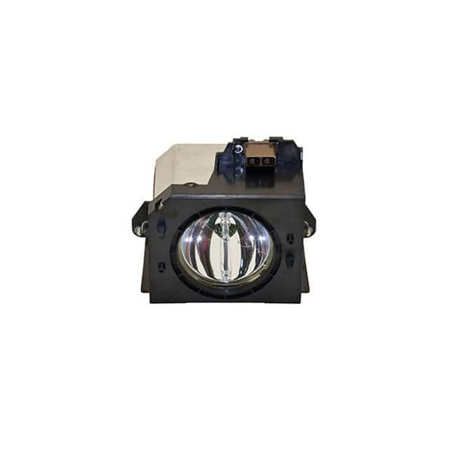
FOR ES BP96-00224A-ER Lamp Design Tutorial: WW-SETA-4 Guide
The FOR ES BP96-00224A-ER lamp from Interlight (SKU WW-SETA-4) is a replacement projection lamp assembly originally specified for DLP televisions using the Samsung BP96-00224A lamp housing. For the electronics experimenter, this part is interesting because it bundles a high-pressure mercury arc lamp with an integrated reflector and wiring harness, giving you a compact, high-intensity light source that behaves much like a constant-current load with a nonlinear ignition characteristic. That makes it an excellent vehicle for learning lamp ballasting, ignition sequencing, and thermal management on a realistic load.
Treat the lamp as a discharge device, not a resistor. It needs a high-voltage ignition pulse (typically 1–5 kV) to strike the arc, then a regulated current in the 1–2 A range to sustain it at roughly 60–90 V. The tutorial circuit below is a simplified DC ballast with ignition assist, suitable for bench learning. Design requirements: 24 V DC input (a beefy bench supply or battery), sustained lamp current of 1.2 A, ignition pulse of at least 2 kV, current limiting to protect the lamp and supply, and thermal cutoff to prevent overheating.
Step 1: Determine the load envelope. Assume lamp arc voltage 70 V at 1.2 A, giving 84 W. Your 24 V rail cannot directly drive that, so you need either a boost topology or a step-up transformer. For a tutorial, use a boost converter followed by a current-sense feedback loop. Required boost ratio: 70/24 ≈ 2.9, comfortably within a simple boost design.
Step 2: Choose switching frequency and inductor. Pick f = 100 kHz. With a peak-to-peak ripple of 30% of 1.2 A (0.36 A), inductor value L = V_in × (1 − V_in/V_out) / (f × ΔI) = 24 × 0.657 / (100k × 0.36) ≈ 438 µH. Round to 470 µH, rated for at least 3 A saturation.
Step 3: Output capacitor. Allow 1% output ripple at 70 V. C = I_out / (f × ΔV) = 1.2 / (100k × 0.7) ≈ 17 µF. Use 22 µF, 100 V electrolytic plus a 1 µF ceramic.
Step 4: Current sense. Place a 0.1 Ω shunt in the lamp return. At 1.2 A the drop is 120 mV, fed to a comparator or a current-mode controller reference.
Step 5: Ignition. A small flyback or a triggered spark gap across the lamp provides the strike pulse. Keep the pulse isolated from the control loop with a series inductor or diode.
BOM rationale: Use a 100 V, 10 A MOSFET for the boost switch; a Schottky diode rated 100 V/5 A for the output; a current-mode PWM IC (e.g., UC3843-class) for loop stability; a 0.1 Ω 1% sense resistor; and a thermal fuse bonded near the lamp housing. The Interlight assembly’s harness should be terminated in a connector matching your board so the lamp can be swapped without soldering.
Simulation tips: Model the lamp as a voltage source (70 V) in series with a small resistance once struck, and as an open circuit before ignition. Simulate the boost loop for startup overshoot; you want current to ramp, not spike. Watch the inductor current in discontinuous mode at low duty and confirm the compensator settles in under 5 ms. Check that the ignition pulse does not forward-bias the output diode.
For the prototype, build the boost stage first and test it into a dummy load (a 60 V, 100 W resistor bank) before connecting the lamp. Verify current regulation at 0.5, 1.0, and 1.2 A. Then add the ignition circuit and test in a darkened room with eye protection. Mount the lamp in its reflector housing with forced air; the BP96 housing expects airflow, and without it the lamp will overheat within minutes.
Performance verification: Measure lamp current with a clamp meter, arc voltage across the lamp terminals, and case temperature with a thermocouple. Target 1.2 A ±5%, 70 V ±10%, and case temperature under 90 °C. Optimize by trimming the sense resistor or adjusting the feedback divider. If ignition is unreliable, increase the pulse energy or add a small preheat current. Document your final duty cycle and efficiency — a well-tuned boost ballast should exceed 85%.