ADAPTOR FOR SELF-SUPPORTING CABLE (XACB961) Design Tutorial
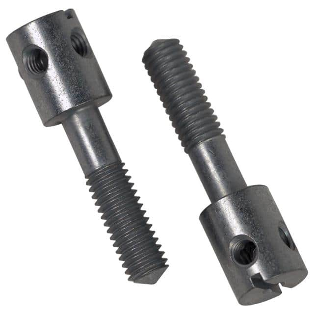
The Schneider Electric XACB961 is a cable adaptor for self-supporting cable, part of the Harmony XAC range of pendant control stations. In plain terms, it is a mechanical strain-relief and entry fitting that lets a suspended, self-supporting control cable terminate cleanly into a pendant enclosure while carrying the cable's own weight and the pull of the operator. It is a good teaching subject because it sits at the interface between electrical design and mechanical design: a circuit only works reliably if the cable entering it is properly anchored, sealed, and relieved of tension. This tutorial walks through designing a small pendant control circuit around the XACB961, treating the adaptor as a first-class design element rather than an afterthought.
Design requirements. Consider a two-button pendant station (start/stop) feeding a 24 VDC control circuit from a fixed control panel. Requirements: cable length up to 10 m suspended vertically; ambient temperature 0 to 55 °C; ingress protection of at least IP65 at the entry point; mechanical retention capable of withstanding a 100 N pull without transferring load to the terminals; and a cable outer diameter matching the adaptor's clamping range. The XACB961 is designed for self-supporting cable, so the cable's own tensile members carry the weight, and the adaptor must grip the outer sheath and/or the support element without crushing the conductors.
Step-by-step design. First, select the cable. A self-supporting control cable with an integral steel or aramid support core, roughly 8 to 12 mm outer diameter, and at least two 0.75 mm² control cores is appropriate. Verify the adaptor's stated cable range against the datasheet before ordering; an out-of-range cable will not seal or grip correctly. Second, calculate the static load. For a 10 m cable at about 0.15 kg/m, the suspended mass is 1.5 kg, or roughly 15 N. Add a dynamic factor of 3 to 4 for operator pulls and snatching, giving a design load of about 45 to 60 N, comfortably inside the 100 N requirement but worth documenting. Third, size the conductors. At 24 VDC and a coil current of 50 mA per contactor, a 0.75 mm² core over 10 m has a loop resistance of about 0.6 Ω, producing a drop of only 0.03 V, which is negligible. Voltage drop is therefore not the limiting factor; mechanical and sealing performance are. Fourth, define the entry geometry: mount the adaptor on the pendant's cable gland position, torque the clamping nut to the manufacturer's specification, and route the support core to an internal anchor point so that no tensile load reaches the terminal block.
BOM rationale. The XACB961 adaptor is the core item because it provides the strain relief and IP seal in one fitting. Pair it with a pendant enclosure rated IP65, two 22 mm pushbuttons (one green momentary start, one red latching stop), a 24 VDC illuminated indicator if desired, and a terminal block rated for the cable gauge. Choose cable with a documented support element rather than plain flexible cable, because the adaptor's purpose is defeated if the cable cannot carry its own weight. Add a cable support clamp or slack loop at the top end for secondary safety. Specify ferrules on all stranded conductors and a torque screwdriver for terminal tightening.
Simulation tips. Before building, model the circuit in a free SPICE or relay-logic tool. Confirm that the start button's seal-in contact holds the contactor after release and that the stop button breaks the holding path. Look for two things: contact bounce at the button, which can cause chatter in a latching circuit, and the behaviour of the circuit if the cable is accidentally pulled, which should fail safe. Mechanically, sketch the cable entry in CAD and check bend radius at the adaptor exit; a tight radius will fatigue the sheath.
Prototype and testing. Assemble the pendant on a bench, then hang it from a hook with the full cable length. Apply a 100 N pull for one minute using a spring scale and inspect for sheath slippage, conductor movement at the terminals, and seal distortion. Perform an IP65 spot check with a light water spray at the entry. Electrically, verify continuity of every core, insulation resistance above 1 MΩ at 500 V, and functional operation of the start/stop sequence twenty times. Finally, do a 500-cycle pull-and-release fatigue test.
Verification and optimization. Record pull-test results, seal condition, and voltage drop at the far end under load. If the sheath creeps, increase the clamping torque within specification or add a secondary clamp. If the bend radius is marginal, fit a boot or shorten the free length. Optimize by standardizing on one cable diameter across the product family so a single adaptor SKU covers all variants, and document the anchor point in the assembly drawing so production never relies on terminal screws for strain relief.