ARJ11B-MBSBQ-A-B-EMU2 Datasheet Guide: 100 BASE-T PCB Jack Explained
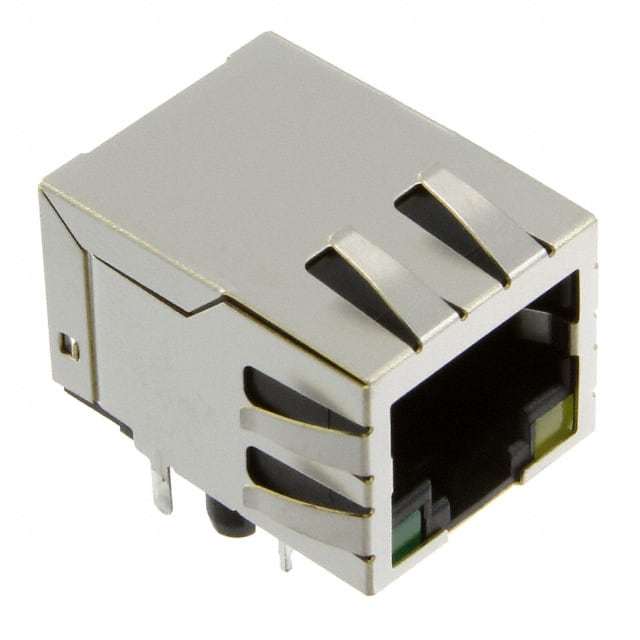
The Abracon ARJ11B-MBSBQ-A-B-EMU2 is a single-port, through-hole, right-angle RJ45 jack with integrated magnetics and LEDs, rated for 100BASE-TX Fast Ethernet applications. Understanding how to read its datasheet is essential for reliable design and for selecting the correct part in volume. This guide walks through the key specification categories and explains what each parameter means in practice for a purchasing and design engineer.
Key electrical specifications. The transformer turns ratio is typically 1:1 for both transmit and receive channels, with a center tap provided for common-mode termination and PoE-style biasing. The datasheet will state the open-circuit inductance (OCL) of the transformer windings, commonly in the range of 350 µH to 400 µH measured at 100 kHz and 100 mV, with a specified DC bias current. OCL directly affects low-frequency return loss and the ability to pass the IEEE 802.3 100BASE-TX template; an undersized OCL produces droop in the transmitted pulse and increased bit error rate over long cable runs. Insertion loss is specified across the 1–100 MHz band, typically under 1.0 dB at low frequencies rising to around 1.5 dB near 100 MHz, while return loss is specified in dB relative to 100 Ω, generally better than −16 dB across the band and tighter around the 10–30 MHz region where impedance mismatches are most visible. Common-mode rejection ratio (CMRR) and crosstalk (near-end and far-end) are also listed, usually in dB, and govern how well the part suppresses EMI and preserves signal integrity in dense switch or router designs. The integrated LEDs have forward voltage and current ratings in the 2.0–2.5 V and 10–20 mA range, depending on color, and should be driven through current-limiting resistors sized from the actual supply rail rather than the nominal LED Vf alone.
Absolute maximum ratings and derating. The datasheet lists maximum operating temperature, typically −40 °C to +85 °C for industrial-grade parts, along with storage temperature, dielectric withstanding voltage (often 1500 Vrms for one minute between primary and secondary), and insulation resistance. These are survival limits, not operating points. In practice, derate the continuous operating temperature to roughly 80% of the rated maximum for long-life telecom and industrial equipment, and derate the LED forward current to no more than 70–80% of the absolute maximum to avoid lumen depreciation and thermal runaway in sealed enclosures. The isolation voltage rating applies to the transformer barrier; if the design includes PoE or surge exposure, verify the datasheet's surge and impulse ratings and confirm that the PCB creepage and clearance meet the relevant safety standard (for example, IEC 60950-1 or 62368-1) rather than relying on the component rating alone.
Typical application circuit. The part is normally placed between the PHY and the RJ45 contacts, with the PHY's differential pairs routed to the transformer primary and the cable-side windings connected to the jack contacts through the integrated termination. The center taps are bypassed to chassis ground through a high-voltage capacitor (typically 1–2 nF, 2 kV) and to signal ground through a parallel resistor-capacitor network that sets the common-mode termination. Bob Smith termination, using 75 Ω resistors and a 1 nF capacitor to chassis, is commonly implemented on the cable side to control common-mode emissions. The LEDs are wired as indicator outputs from the PHY or controller, with the anode tied to the supply through a resistor and the cathode to the driving pin. Ensure the magnetics' center-tap biasing matches the PHY's requirements; some PHYs require a specific DC bias on the receive pair, and the datasheet's transformer schematic will indicate whether the center taps are internally connected or brought out separately.
Pin configuration and package. The datasheet provides a mechanical drawing with pin numbering, the through-hole footprint, and the LED pin assignments, which vary between parts even within the same family. Confirm the pinout against the drawing rather than assuming a standard, and check the recommended PCB hole diameter, pad size, and keep-out for the connector body. The right-angle, through-hole format requires adequate annular ring and solder fillet; the datasheet's recommended footprint should be followed exactly, including the shield tabs and any locating posts, to ensure mechanical retention and EMI shielding contact with the chassis.
Thermal management. The primary heat sources are the LEDs and, in PoE applications, the transformer windings carrying DC current. The datasheet's temperature rise curves versus LED current and ambient temperature guide the resistor selection. Provide copper pour and thermal relief around the LED pins and, for PoE designs, ensure the magnetics' DC current rating is not exceeded, since saturation reduces inductance and increases losses. In sealed enclosures, measure the actual local ambient at the connector rather than the system ambient.
Reading the curves and timing diagrams. The characteristic curves—insertion loss, return loss, crosstalk, and OCL versus frequency—are measured under specified test conditions (source impedance, load, bias) that must be matched to your application for the numbers to be meaningful. Pay attention to the frequency axis and whether the curves are typical or guaranteed limits. Timing information, where present, relates to the LED switching or to the transformer's pulse response; interpret rise time and overshoot against the 100BASE-TX pulse mask. When in doubt, request the full qualification report and confirm that the SKU's test conditions align with your PHY vendor's recommended magnetics specification.