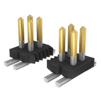
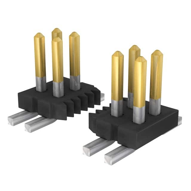
FTS-115-01-L-DV Datasheet Guide: 30-Pin 1.27mm SMD Header
The Samtec FTS-115-01-L-DV is a 30-position, dual-row, surface-mount header from the FTS (Fine Pitch Terminal Strip) family, built around a 1.27 mm (0.050 in) pitch. When reading its datasheet, the first thing an engineer should internalize is that this is a board-to-board or board-to-cable interconnect whose electrical behavior is dominated by contact resistance, plating, and dielectric rather than by any active semiconductor characteristic. The datasheet's electrical table is typically anchored by a contact resistance of around 10 mΩ maximum, a dielectric withstanding voltage on the order of 500 VAC, and an insulation resistance of 5,000 MΩ minimum. In practice, the contact resistance figure tells you how much voltage drop and self-heating you can expect per mated pin under load; with 1.27 mm pitch terminals, current-carrying capability is modest (often quoted around 1–2 A per contact depending on derating and mating connector), so the 10 mΩ figure matters most when you are paralleling pins for power or when you are budgeting IR drop across a long signal path. The insulation resistance and dielectric strength numbers are your guardrails for creepage and clearance in higher-voltage or isolation-sensitive designs, and the "L" in the part number denotes the plating option (typically a light gold flash over nickel), which directly affects contact resistance stability and mating-cycle endurance.
Absolute maximum ratings on this header deserve careful reading because they are frequently misapplied. Samtec data sheets for the FTS series generally specify a temperature range of −55 °C to +125 °C for the insulator and a per-contact current rating that is valid only under defined test conditions, usually with a specified temperature rise (commonly 30 °C) and with all contacts energized. The critical derating consideration is that current rating is not a single number but a curve: as ambient temperature rises toward the upper limit, allowable current falls, and when multiple adjacent contacts carry current simultaneously, mutual heating reduces the per-pin allowance further. A 30-position dual-row header with all pins loaded will run hotter than a sparsely populated one, so a conservative design derates to perhaps 50–60 % of the single-contact rating for continuous power delivery. Voltage derating follows the same logic: the dielectric withstanding voltage is a test voltage, not an operating voltage, and working voltage should be set well below it, especially at altitude or in humid environments where the effective clearance between 1.27 mm-pitch contacts is small.
In a typical application circuit, the FTS-115-01-L-DV appears as the board-side half of a mated pair, often carrying a mix of single-ended digital signals, a differential pair or two, and a small number of power and ground returns. Because the pitch is fine and the rows are closely spaced, crosstalk between adjacent signal pins is the dominant electrical concern rather than series resistance. A practical interpretation is to assign ground returns interleaved with high-speed signals, keep the rise times in mind (the header itself is largely transparent below a few hundred MHz, but its pin inductance and mutual capacitance begin to matter as edge rates shorten), and treat the connector as a small lumped discontinuity. For power delivery, distribute current across multiple pins and verify that the total IR drop plus connector self-heating stays within the derated budget. The datasheet's suggested mating connector and stack height should be honored, since contact wipe and normal force depend on the specified mating geometry; substituting a non-matching header can degrade contact resistance and reliability.
Pin configuration for the FTS-115-01-L-DV is straightforward but easy to misread: the "115" indicates 15 positions per row, and the "D" indicates dual row, yielding 30 total contacts, while "V" denotes the vertical surface-mount orientation. The datasheet's recommended land pattern is the authoritative source for footprint dimensions, pad size, and solder-mask clearance; deviating from it is the most common cause of solder-joint defects on fine-pitch SMD headers. Package considerations include coplanarity of the SMT tails, the need for adequate paste volume to avoid bridging at 1.27 mm pitch, and the mechanical support the housing provides against lateral forces during mating. Engineers should also confirm the tail length and stack height against the mating receptacle, because the "01" in the part number encodes a specific lead style and the overall mated height is fixed by that combination.
Thermal management for a passive header is mostly about current density and board-level heat spreading. The datasheet does not provide a junction-to-ambient thermal resistance because there is no junction; instead, you infer thermal behavior from the current derating curve and from temperature-rise test conditions. Keep power-carrying pins distributed rather than clustered, provide copper pours on the PCB pads to conduct heat away from the solder joints, and avoid routing the header through a thermal shadow where neighboring components preheat the connector. For high-reliability designs, verify the mated assembly's temperature rise empirically under worst-case load rather than relying solely on the datasheet's nominal rating.
Finally, the characteristic curves and any timing or performance plots in the datasheet must be read with attention to their test conditions. Curves showing contact resistance versus mating cycles, temperature rise versus current, or insertion/withdrawal force versus displacement are all conditioned on specific plating, mating connector, and environmental parameters. The current-versus-temperature derating curve is the single most important plot for power budgeting; read the axis labels carefully, note whether the curve is for a single contact or an all-contacts-energized condition, and apply your own margin. Insertion force curves help predict mating effort and connector wear, while any signal-integrity plots should be interpreted as representative rather than guaranteed, since actual performance depends on the PCB launch, trace routing, and the mating half. Treat every curve as a design aid bounded by its stated test conditions, and when in doubt, request Samtec's qualification test report for the specific plating and mating combination you intend to use.