M12 A-Code 4-Pin Female Troubleshooting: Fix Common Faults Fast
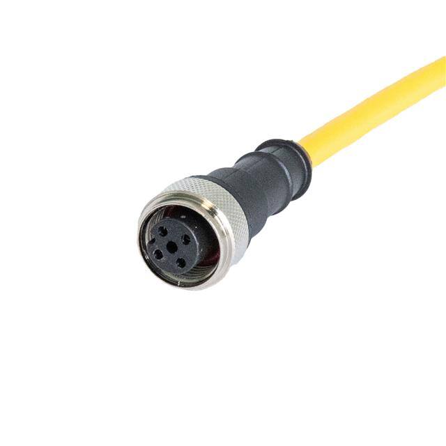
When a HARTING M12 A-coded 4-pin straight female connector (SKU 21350200416010) is involved in a field failure, the connector itself is rarely the first suspect—but it is frequently the root cause after a few layers of investigation. This guide walks through the practical realities of debugging circuits that use this component.
Typical failure modes and root causes. The most common issue is intermittent signal loss on one or more pins. Root causes include incomplete mating (the connector clicked but wasn't fully seated), contamination or moisture ingress at the interface, and mechanical damage to the female contacts from repeated mating or misaligned insertion. A second common failure is pin-to-pin shorting caused by water bridging the contacts or by debris in the coupling nut area. Less common but documented: cracked solder joints on the PCB-side termination when the connector is used in high-vibration environments without strain relief. Finally, corrosion on the gold-plated contacts from exposure to washdown chemicals will manifest as rising contact resistance over time.
Step-by-step debugging methodology. Start by disconnecting and visually inspecting the mating interface under magnification—look for bent contacts, dark arcing marks, or green corrosion. Next, measure continuity pin-by-pin from the cable side to the PCB side while flexing the cable; a resistance that jumps above a few ohms or goes open indicates a bad termination. Then check insulation resistance between adjacent pins with a megohmmeter at 500 VDC—anything below 100 MΩ suggests contamination or moisture. Finally, verify the circuit downstream: many "connector failures" turn out to be a failed sensor or a blown protection diode on the board. Only after these steps should you replace the connector.
Common mistakes in schematic design and PCB layout. A frequent error is omitting ESD and surge protection on the signal pins; the M12 connector is often the first thing an operator touches, and without a TVS diode or transient suppressor, a static discharge can kill the downstream transceiver. Another mistake is routing the four pins with inadequate creepage—if the design carries 24 V on pin 1 and a low-level analog signal on pin 2, insufficient spacing invites leakage under humidity. On the layout side, a classic error is placing the connector footprint too close to the board edge so the coupling nut cannot rotate fully; this causes partial mating and intermittent faults. Also, ensure the through-hole pads have adequate annular rings and thermal reliefs if hand-soldering, because cold joints here are a leading cause of field returns.
Verifying component authenticity and quality. Counterfeit M12 connectors are common in distribution channels. Check the HARTING branding on the coupling nut and the molded body—genuine parts have crisp, consistent laser marking. Inspect the contact plating: authentic gold plating is uniform and bright; cheap substitutes often show thin or uneven plating that wears through after a few mating cycles. Verify the part number against HARTING's documentation and confirm the A-coding keyway geometry matches the drawing. If you have a known-good sample, compare weight and thread pitch; counterfeit units frequently use softer brass that strips under torque.
Measurement techniques and test equipment. Use a four-wire milliohm meter to measure contact resistance—a good mated pair should read well under 10 mΩ. A megohmmeter handles insulation resistance checks. For intermittent faults, a data logger or oscilloscope with a long memory capture on the signal line can catch dropouts during vibration or thermal cycling. A thermal camera helps spot a connector running hot due to high contact resistance. For field work, a simple multimeter with a continuity beeper and a set of fine probes is usually sufficient, but always test with the system powered down unless you are measuring voltage.
When to suspect the component versus the surrounding circuit. Suspect the connector when the fault follows the cable when you swap it to another port, when flexing the cable reproduces the fault, or when contact resistance exceeds spec after cleaning. Suspect the surrounding circuit when the fault persists with a known-good cable, when multiple connectors on the same board fail simultaneously, or when the failure correlates with a specific operating mode rather than physical movement.
Real-world case studies. In one case, a packaging machine reported random encoder dropouts. The M12 connector passed continuity and insulation tests, but a thermal camera showed pin 3 running 15°C hotter than the others. The root cause was a cold solder joint on the PCB pad, aggravated by vibration—reflowing the joint solved it. In another case, a washdown application saw rising contact resistance on all four pins within six months. The connector was genuine, but the customer had used a non-sealed mating cable and water wicked into the interface. Switching to an IP67-rated mating cable and adding a drip loop eliminated the problem. A third case involved intermittent shorts that appeared only in humid weather; the culprit was conformal coating that had bridged two pins during assembly, a layout issue rather than a connector defect.