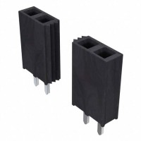
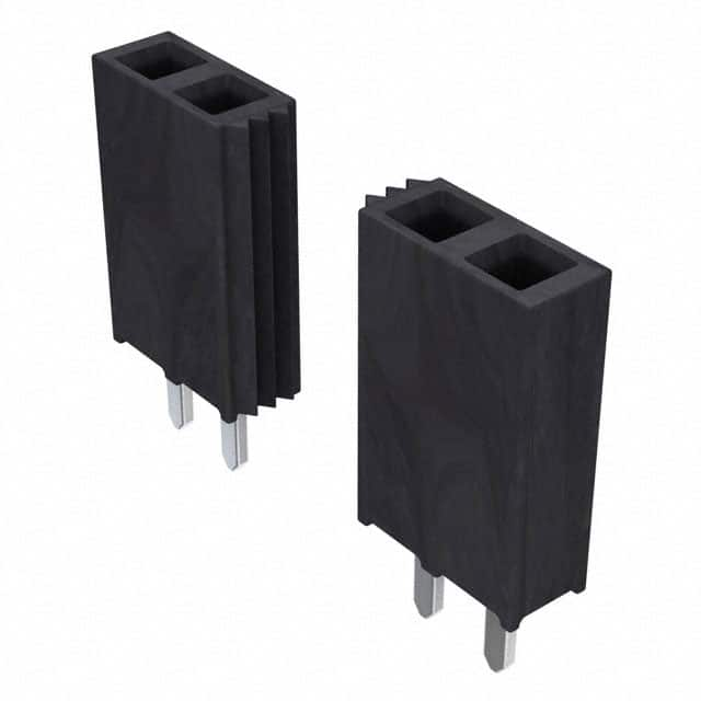
SSW-126-01-S-S Datasheet Guide: 26-Position Gold PCB Receptacle Explained
The Samtec SSW-126-01-S-S is a 26-position, single-row, through-hole receptacle strip from the widely used SSW (Socket Strip, Wave solderable) series, built on a 0.100 inch (2.54 mm) pitch grid. Decoding the part number is itself the first lesson in datasheet literacy: SSW identifies the socket strip family, 126 denotes 26 positions, 01 is the standard insulator height (0.095 inch body height, giving a nominal mating pin entry depth appropriate for 0.025 inch square posts), S indicates the gold-plated contact system (Samtec's "S" plating is a performance-grade gold flash over nickel underplate on the contact and a matte tin on the tail), and the final S specifies a single-row configuration. Engineers should always cross-check the suffix against the current Samtec catalog page, because plating callouts and insulator heights change between series revisions, and a distributor SKU can lag an internal revision. A quick sanity check is to verify the position count against the physical body length: 26 positions at 2.54 mm pitch yields approximately 63.5 mm of contact span, and the datasheet drawing will show the exact overall length including end margins.
Electrically, the SSW series is specified for a current rating of 3 A per contact (with all contacts energized, in still air at 25 degrees C) and an insulation resistance of at least 5000 megohms at 500 VDC. The working voltage is typically rated at 465 VAC/VDC maximum, derived from the insulator material's dielectric strength and the 2.54 mm pitch spacing. In practice, these numbers should be treated as a starting envelope rather than a guarantee, because current capacity is dominated by the total temperature rise of the mated contact pair, not the connector alone. The gold flash is intended for low-level signal and low-mating-cycle applications; if the design calls for repeated mating or a high-reliability contact resistance, a thicker gold specification (such as the "S" versus "G" plating options) should be reviewed with the datasheet's plating thickness callout, which is typically 0.76 microns minimum over 1.27 microns of nickel. Contact resistance is quoted at around 10 milliohms maximum, but the real number depends on the mating post finish and insertion depth, so a system-level measurement is the only reliable figure.
Absolute maximum ratings for this connector family are less about voltage flashover and more about mechanical and thermal limits. The insulator is typically a glass-filled thermoplastic (often PBT or LCP depending on the series variant), rated for an operating temperature range of -55 to +125 degrees C. Exceeding the upper limit will not cause immediate failure but will accelerate creep and loss of contact normal force, so derating to roughly 80 percent of the rated temperature rise is prudent in enclosed or high-vibration environments. The current derating curve in the datasheet shows the familiar downward slope: at 3 A per contact the temperature rise is near the specified limit, and derating to about 2 A per contact provides margin for adjacent-contact heating and for connectors mounted in still air without forced convection. Mechanical ratings—insertion force per contact (typically around 0.5 to 1.5 N) and withdrawal force—matter for panel and board-to-board designs, and the cumulative insertion force across 26 positions can reach tens of newtons, which must be accounted for in the mating hardware.
The typical application circuit for this part is a board-to-board or board-to-wire signal and low-power distribution interface: a 0.025 inch square post header mates with the receptacle, and the through-hole tails are wave- or hand-soldered into a 2.54 mm grid on the host PCB. Because the part is single-row, the layout is straightforward, but the pin configuration drawing should be read carefully: the datasheet shows the contact numbering convention (usually pin 1 at the end nearest the polarization feature) and the recommended PCB hole pattern, which for this series is a 1.0 mm finished hole diameter with a 1.8 mm annular ring. Verify the drill chart against your fab's capabilities, and remember that the through-hole tails require adequate solder fillet height on both sides in a plated-through design. There is no integral polarization key on the standard SSW, so a mating header with a keying feature or a silkscreen orientation marker is the practical way to prevent reverse insertion.
Thermal management guidance follows from the derating discussion: the connector is not a heat sink, and its temperature rise is a function of the current through each contact and the thermal resistance to the surrounding air. In a 26-position strip carrying 3 A on every pin, the middle contacts run hotter than the end contacts because of mutual heating, so the datasheet's single-value current rating is a best-case figure. For high-current or high-density designs, stagger the load across non-adjacent pins, provide airflow across the board, and consider a higher-temperature insulator variant. Finally, when interpreting the characteristic curves, note the axes carefully: the current-versus-temperature-rise curve is measured with all contacts energized, whereas the insertion-force curve is per contact and measured at a specified insertion speed. A curve read without its test conditions is a common source of over-design, so always confirm the measurement basis—number of energized contacts, air velocity, and mating post finish—before applying the data to a production decision.