MMCX to N Cable Design Tutorial: RG174 18-Inch Assembly Guide
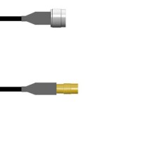
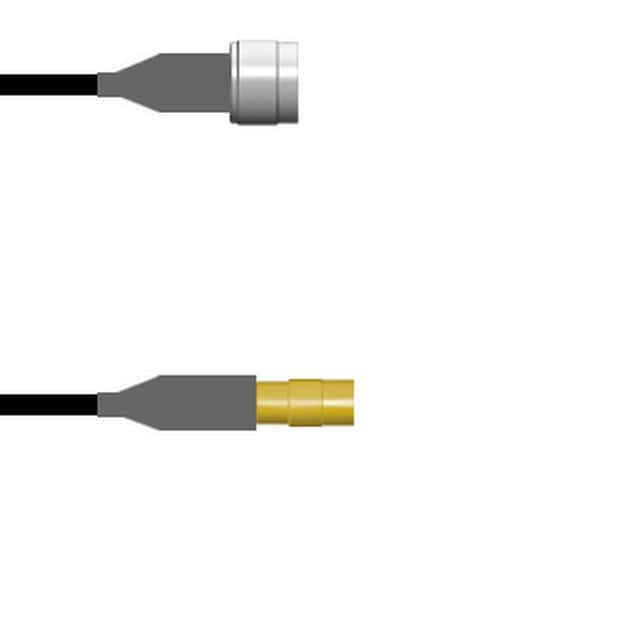
The Amphenol Custom Cable CBL ASY MMCX-N J TO P RG174 18" (SKU: Q-2I01J0003018i) is an 18-inch assembly that transitions an MMCX jack to an N-type plug over flexible RG174 coax. It is a handy building block for any bench project that needs to connect a compact MMCX-equipped board to a rugged N-type test port or antenna without a tangle of adapters. In this tutorial we use it as the RF output link in a 433 MHz low-power telemetry transmitter front end, a realistic scenario where the radio module sits on a small board and must reach a lab-grade N connector on an enclosure panel. What makes this cable suitable here is its 50 ohm characteristic impedance, its mechanical flexibility for tight enclosures, and the fact that MMCX gives you a push-on, snap-lock interface for quick board swaps while the N plug provides a durable threaded connection for repeatable measurements.
Design requirements. Target band: 430–435 MHz. Output power: +10 dBm into 50 ohms. Insertion loss budget through the cable: under 1.0 dB at 433 MHz. Return loss at the N port: better than 15 dB. The RG174 assembly is specified for roughly 0.3–0.5 dB loss per foot at this frequency, so 18 inches lands comfortably inside budget. Physical constraints: the cable must bend through a 25 mm radius inside the enclosure and the MMCX end must mate with a right-angle board jack.
Step-by-step design. First, confirm impedance continuity: the PA output, the MMCX jack, the cable, and the N plug are all 50 ohms, so no matching network is needed at the cable itself. Second, size the PA load: with +10 dBm (10 mW) into 50 ohms, peak voltage is V = sqrt(2·P·R) ≈ 1.0 V, well within the driver's swing. Third, account for cable loss in the link budget: at 0.4 dB cable loss, 10 mW at the board becomes about 9.1 mW at the N port, or +9.6 dBm. Fourth, add a 6 dB resistive pad between the PA and the MMCX jack only if you need to protect the PA from open-circuit reflections during bench testing; otherwise a DC-blocking capacitor (100 pF, 0402) at the board jack is sufficient. Fifth, plan grounding: bond the MMCX jack shell to the board ground plane with at least four vias to keep the shield reference solid.
Component selection rationale. The cable assembly is the fixed anchor of the BOM. Pair it with an MMCX right-angle PCB jack (50 ohm, gold-plated) so the snap-lock mates reliably. Use an N-type bulkhead jack on the enclosure panel to accept the cable's N plug, with a short internal pigtail or direct mount to the test port. For the transmitter, choose a 433 MHz ISM-band PA module rated at +13 dBm so you run it backed off, improving linearity and thermal margin. Add a 100 nF plus 10 µF decoupling pair on the PA supply, a 100 pF DC block at the MMCX jack, and a 50 ohm terminator for reflection tests. Keep every RF joint soldered, not socketed, except the MMCX itself.
Simulation tips. Model the RG174 run in your simulator as a lossy transmission line: set Z0 = 50 ohms, velocity factor about 0.66, and loss to match the datasheet (roughly 0.4 dB at 433 MHz for 18 inches). Sweep 300–600 MHz and look for two things: flat insertion loss across the band (no ripple means the connectors are well matched) and return loss at both ends. Watch for a resonance if the cable is coiled tightly; a half-wave at 433 MHz is about 23 cm in the dielectric, so an 18-inch (46 cm) run is near two half-waves and small impedance bumps will show up. In simulation, add a 0.2 ohm series contact resistance at the MMCX to approximate real connector behavior.
Prototype build and testing. Solder the MMCX jack to the board, snap the cable on, and torque the N plug finger-tight to the bulkhead. Measure with a VNA: calibrate at the N end, then record S11 and S21 from 300 to 600 MHz. Confirm insertion loss under 1 dB and return loss better than 15 dB at 433 MHz. Next, key the transmitter into a 50 ohm load and measure output at the N port with a power meter; expect about +9.5 dBm. Flex the cable through its bend radius while watching the power meter for jumps greater than 0.2 dB, which would indicate a marginal connector crimp.
Verification and optimization. If return loss is marginal, first reflow the MMCX jack ground vias, then check that the N bulkhead is bonded to the chassis. If insertion loss exceeds budget, shorten the run or replace RG174 with a lower-loss cable while keeping the same MMCX-to-N transition. Finally, run a 24-hour thermal soak at +10 dBm and re-measure S21 to confirm the assembly is stable; a drift under 0.1 dB validates the design for production.