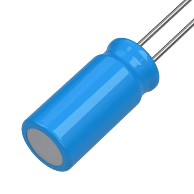
Application Note: 2.2uF 100V Radial Aluminum Capacitor (MAL203859228E3)
The MAL203859228E3 from Vishay's BC Components 038 RSM series is a radial-leaded aluminum electrolytic capacitor rated 2.2 µF ±20% at 100 V, packaged in a compact case (approximately 5 × 11 mm) intended for through-hole mounting on 2.5 mm lead spacing. Its combination of moderate capacitance, high voltage rating, and small footprint makes it well suited as a local bulk/decoupling element in offline and high-voltage rails, as a coupling or timing capacitor in analog signal paths, and as a smoothing element in low-current bias supplies. Because 2.2 µF is a small value for an electrolytic, it is most effective when it complements rather than replaces ceramic capacitors: use it where energy storage over millisecond time scales or damping of low-frequency impedance is needed, and rely on ceramics for high-frequency bypass.
Recommended topologies include RC and RCR low-pass filters on supply rails feeding sensitive analog blocks, AC coupling between stages where the 100 V rating provides margin against fault conditions, and snubber or damping networks across low-power switching nodes. In all of these, observe polarity strictly—reverse bias degrades the oxide layer and can cause catastrophic failure. Design the circuit so the capacitor never sees more than its 100 V rating under worst-case transients, including turn-on overshoot; a transient suppressor or a series resistor is prudent where inductive kickback is possible. Keep ripple current modest, as small radial electrolytics have limited ripple capability, and derate the working voltage to roughly 70–80 percent of rated value for long-life applications.
Supporting passives should be chosen with the electrolytic's parasitics in mind. Place a 100 nF ceramic (X7R, 100 V or higher) directly in parallel to handle high-frequency currents the electrolytic cannot, and consider a 10–100 nF film capacitor in parallel where low dielectric absorption matters, such as sample-and-hold or audio coupling circuits. For timing applications, note that aluminum electrolytics have wide tolerance and significant leakage and temperature drift; if timing accuracy matters, use a film or ceramic part instead and reserve the electrolytic for bulk functions. Series resistors in filter networks should be sized to limit inrush and ripple current, and any bleed resistor across the capacitor should be checked for leakage current dominance in high-impedance nodes.
On the PCB, keep lead lengths short and route the capacitor's return path directly to a low-impedance ground or rail plane. Because the part is through-hole, place it on the same side as the main heat-generating components only if ambient temperature stays comfortably below the rated category temperature; electrolytic life halves roughly for every 10 °C rise, so position it away from regulators and power resistors. Provide adequate annular ring and solder fillet on both pads, and avoid routing sensitive high-impedance traces beneath the body, since the aluminum can and electrolyte can couple noise. If the board undergoes conformal coating or potting, verify the coating does not trap solvent against the rubber seal.
For EMC, the electrolytic is primarily a low-frequency energy reservoir and damping element rather than an RF bypass. Use it to stabilize the input of linear regulators and to damp LC resonances formed by cable inductance and on-board ceramics; a small series resistance (a few ohms) in series with the capacitor can tame peaking in filter designs. Keep the loop area between the capacitor, its load, and the return path small, and pair it with a ceramic at the point where high-frequency currents actually flow. In conducted-emissions testing, the electrolytic helps suppress low-frequency ripple but will not address switching harmonics; plan ceramic and ferrite mitigation separately.
Common pitfalls include installing the part reversed—mark the cathode clearly in silkscreen and verify assembly orientation—and assuming the 20 percent tolerance is tighter than it is when calculating filter corners. Another frequent error is using the capacitor in a high-ripple switching supply without checking ripple current ratings, leading to heating and shortened life. Designers also sometimes overlook leakage current in high-impedance or precision circuits, or mount the part flush against a hot component. Finally, do not substitute a low-voltage part in a 100 V position during prototyping; the voltage margin is a key reason this specific SKU was selected.
For prototyping, hand-solder with a temperature-controlled iron and avoid excessive dwell time on the leads, which can damage the seal. On the bench, verify polarity and rated voltage before power-up, then measure DC leakage after a few minutes of soak at rated voltage; expect values in the low microamp range and flag anything dramatically higher. Use a current probe or a small series shunt to observe inrush and ripple, and check capacitance with an LCR meter at 120 Hz or 1 kHz. Thermal-cycle and burn-in the prototype at elevated ambient to confirm margin, and inspect the seal area for electrolyte weeping after vibration or thermal stress. Document orientation and lot information so field returns can be traced.
CAP ALUM 2.2UF 20% 100V RADIAL
Vishay Beyschlag/Draloric/BC Components | MAL203859228E3 | $0.43