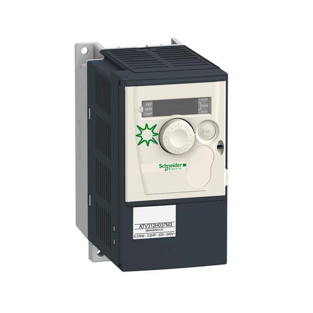
ATV312H037M3412 Variable Speed Drive Design Tutorial
The Schneider Electric ATV312H037M3412 is a compact variable speed drive from the Altivar 312 family, rated 0.37 kW (0.5 hp) for three-phase 380–500 V motors. What makes it ideal for a teaching tutorial is its balance of simplicity and capability: it offers analog and logic I/O, Modbus RTU, sensorless flux vector control, and a built-in operator interface, yet it mounts on DIN rail and configures through straightforward parameters. You get realistic industrial behavior—ramps, current limits, fault handling—without a complex engineering toolchain, so the focus stays on design decisions rather than software setup.
Design requirements and specifications. Target a small conveyor or fan retrofit: a 0.37 kW three-phase induction motor, 400 V supply, variable speed from 10 to 50 Hz, 5-second acceleration and deceleration ramps, and remote start/stop with a speed potentiometer. Add two safeguards: a motor thermal relay input and an emergency stop that triggers a freewheel stop. Specify 150% overload for 60 seconds, ambient up to 40 °C, and IP20 enclosure mounting. The drive accepts single-phase 200–240 V or three-phase 380–500 V depending on the model suffix; confirm your unit's nameplate before wiring, since the M3412 designation indicates the three-phase 380–500 V variant.
Step-by-step design process. First, size the drive to the motor: continuous current must exceed motor full-load current at rated voltage. A 0.37 kW, 400 V motor draws roughly 1.0–1.1 A; the ATV312H037M3412 delivers about 2.2 A continuous, giving comfortable margin for ramp and load transients. Second, verify supply compatibility: three-phase 400 V matches the drive's input range, and a 6 A class gG fuse or C-curve breaker protects the input. Third, calculate braking needs. For a conveyor with modest inertia, the deceleration torque at a 5 s ramp stays below the motor's rated torque, so no braking resistor is required; if you later shorten the ramp below 2 s, check that DC bus overvoltage does not trip—estimate regenerative energy and add a resistor if needed. Fourth, assign I/O: LI1 for forward run, LI2 for reverse, AI1 for the 0–10 V speed reference, and a logic output for fault indication. Set parameters accordingly: Fr1 = AI1, ACC = 5 s, dEC = 5 s, LSP = 10 Hz, HSP = 50 Hz, and configure LI1/LI2 as 2-wire control. Fifth, wire the thermal relay contact into a stop input and set the fault response so the drive coasts on overload.
Component selection rationale. The drive itself is chosen for its integrated EMC filter and Modbus port, which avoids extra hardware for a remote HMI later. Use shielded motor cable (four-core, 1.5 mm²) to limit radiated noise, a 10 kΩ linear potentiometer for the reference (low current draw, stable), and a 24 V DC auxiliary supply only if you add indicator lamps. Fuses must be the drive manufacturer's recommended class and rating—undersized fuses nuisance-trip on inrush, oversized ones fail to protect the semiconductors. Keep control wiring separated from motor cables by at least 100 mm and ground the shield at both ends.
Simulation tips. Before building, model the motor-load pair in a drive sizing tool or spreadsheet: plot speed, torque, and current during the 5 s ramp and confirm peak current stays under 150%. Check the DC bus voltage during deceleration against the overvoltage threshold; if the simulated rise approaches it, either lengthen the ramp or plan a resistor. Also simulate a stuck-load fault to verify the drive's current limit holds rather than tripping instantly.
Prototype build and testing. Mount the drive on DIN rail in an enclosure with 50 mm clearance above and below for airflow. Wire power first with the motor disconnected, then energize and confirm the display shows ready with no faults. Next, connect the motor uncoupled, run at 10 Hz, and verify rotation direction; swap two motor phases if reversed. Couple the load, run the full 10–50 Hz sweep, and log motor current. Test each safety path deliberately: open the thermal relay contact, press emergency stop, and remove the speed reference to confirm the expected stop types. Finally, run a 30-minute soak at 40 Hz and check heatsink temperature and terminal tightness.
Performance verification and optimization. Measure actual ramp times with a tachometer or the drive's speed display and adjust ACC/dEC to match specification. If current oscillates at low speed, enable sensorless vector mode and run auto-tuning. Trim the minimum frequency to avoid motor overheating at very low speed, and verify that fault logs capture each test event. Document final parameter values so the setup is repeatable—this parameter sheet becomes your commissioning record.