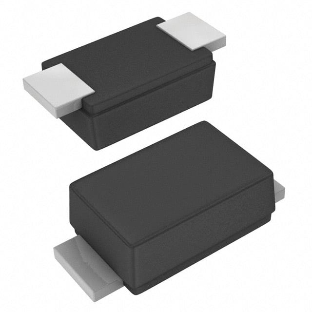
Designing with the ES07D-GS08 200V Diode: A Practical Tutorial
The Vishay ES07D-GS08 is a general-purpose rectifier in a compact DO-219AB (SMF) surface-mount package rated at 200 V reverse voltage and 500 mA forward current. Its fast recovery time (typically 25 ns) and low forward drop make it a versatile choice for small-signal rectification, freewheeling, and protection duties. For this tutorial we will use it as the freewheeling diode in a low-power buck converter, a role where its speed, voltage margin, and tiny footprint all matter. The part is inexpensive, widely stocked, and forgiving of beginner mistakes, which makes it ideal for learning diode selection in switching circuits.
Design requirements. We will build a 12 V to 5 V buck converter delivering 300 mA (1.5 W) at 100 kHz switching frequency. The freewheeling diode must handle the inductor current during the off-time, block the full input voltage plus margin, and recover quickly enough to keep switching losses low. Key specs: average forward current 300 mA (60% of rating), peak repetitive current about 450 mA, reverse voltage 12 V (6% of the 200 V rating, giving large safety margin), and junction temperature below 100 °C in still air.
Step-by-step design. First, compute the duty cycle: D = Vout/Vin = 5/12 = 0.417. The inductor sees a peak current of Iout plus half the ripple; with a 100 µH inductor and 100 kHz switching, ripple is roughly 0.6 A, so peak current is about 0.6 A. This exceeds the 500 mA rating momentarily, so either increase the inductor to 220 µH (ripple drops to about 0.27 A, peak 0.44 A) or accept brief excursions, since the ES07D tolerates 1 A non-repetitive surges. Choose the 220 µH inductor for margin.
Next, estimate conduction loss: P = Vf × Iavg × (1−D). With Vf ≈ 0.9 V at 300 mA, P ≈ 0.9 × 0.3 × 0.58 = 0.16 W. Thermal resistance of the SMF package is roughly 250 °C/W junction-to-ambient on minimal copper, giving a 40 °C rise—acceptable, but add a small copper pour under the cathode for margin. Switching loss is negligible at 100 kHz given the 25 ns recovery. Finally, verify reverse voltage: the diode blocks Vin plus ringing, perhaps 18 V peak. The 200 V rating provides more than 10× headroom, so no snubber is strictly needed, though a small RC across the diode reduces EMI.
BOM and component rationale. The ES07D-GS08 handles freewheeling. Pair it with a 220 µH, 1 A shielded inductor (low core loss at 100 kHz), a 100 µF low-ESR electrolytic plus 10 µF ceramic on the output, and a 47 µF input capacitor to absorb switching ripple. The controller can be a simple 555-based PWM or a dedicated buck IC such as the LM2596 configured for 5 V. A 10 Ω/100 pF snubber across the diode is optional. All parts are common, and the diode's SMF footprint saves board space compared with a DO-41 through-hole part.
Simulation tips. Model the diode in SPICE with a forward voltage of 0.9 V, series resistance 0.5 Ω, and junction capacitance around 10 pF. Set the recovery time to 25 ns so switching transients appear realistic. Watch three waveforms: inductor current (should stay continuous at 300 mA load), diode reverse voltage (check for ringing above 20 V—if present, add the snubber), and diode current during the off-time (confirm it never exceeds 600 mA). Also monitor junction temperature using a thermal model; a simple RC network with 250 °C/W works. If the simulation shows excessive ringing, increase the snubber capacitor to 220 pF.
Prototype build and testing. Assemble on a two-layer board with a ground plane; keep the diode loop (input cap, diode, inductor) short to minimize parasitic inductance. Use 0.5 mm traces for the 300 mA path. Before powering up, verify polarity with a multimeter—the cathode band marks the bar. Apply 12 V through a 1 A current-limited supply and check no-load output first (should be near 5 V). Then load with a 16 Ω resistor (300 mA) and measure output ripple with a scope (expect under 50 mV with the ceramic cap). Use a thermal camera or thermocouple on the diode body; it should stay below 70 °C.
Verification and optimization. Sweep load from 50 mA to 400 mA and record efficiency; expect 80–85%. If the diode runs hot, add copper area under the cathode pad—doubling the pour can cut thermal resistance by 40%. If output ripple is high, add a second 10 µF ceramic. Check reverse recovery at the switching node: a clean edge with little overshoot confirms the diode is fast enough. For higher-current variants, the ES07D's 200 V margin lets you push to 400 mA with the same layout, though consider a larger package above that. Document your final measurements and keep the snubber values in the BOM as tuning options.
DIODE GP 200V 500MA DO219AB
Vishay General Semiconductor - Diodes Division | ES07D-GS08 | $0.43