AE8 8C 8#12 SKT Plug Design Tutorial: M83723/95W18086-LC Guide
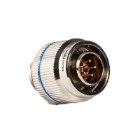
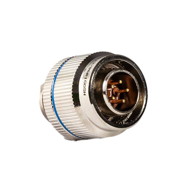
The Conesys M83723/95W18086-LC (SKU AE8 8C 8#12 SKT PLUG) is a circular MIL-DTL-83723 Series III connector with an 18-08 insert arrangement: eight size 12 socket contacts in a bayonet-coupled plug shell. The "W" finish denotes a cadmium-over-nickel plating for corrosion resistance, and the "-LC" suffix means it ships without contacts (less contacts), so you crimp and insert your own size 12 pins. This connector is ideal for a hands-on tutorial because it forces you to think about real interconnect design: contact sizing, current derating, wire gauge, strain relief, and environmental sealing. Its 8-position layout maps cleanly onto a motor-drive or sensor-harness project, and the socket side (plug) is the removable half, which makes bench testing easy.
Design requirements. We will build a 3-phase brushless DC motor harness with hall-effect feedback routed through the connector. Requirements: 48 VDC bus, 15 A per phase continuous, 3-phase power (3 contacts), 5 hall signals plus common (4 contacts), and one spare. Each phase must carry 15 A with margin. The size 12 contact in this series is rated for roughly 23 A with 12 AWG wire, so derate to 70 percent gives about 16 A — acceptable, but we will verify thermal margin. Signal contacts carry under 1 A each. Operating temperature range: -55 to +125 °C per the MIL spec; our harness must survive 85 °C ambient near the motor. Ingress protection target: IP67 when mated with the corresponding receptacle.
Step-by-step design. First, assign contacts. Size 12 positions 1-3 carry phases A, B, C on 12 AWG silicone-insulated wire. Positions 4-7 carry Hall A, B, C, +5 V, and ground on 22 AWG. Position 8 is spare. Second, compute voltage drop: 12 AWG copper is 5.2 mΩ/ft. For a 3 ft run, round-trip resistance is 2 × 3 × 0.0052 = 0.031 Ω. At 15 A, drop is 0.47 V, or about 1 percent of 48 V — fine. Power dissipation per contact: I²R = 225 × 0.0156 = 3.5 W over the run, but only the contact interface matters for the connector: a size 12 crimp contact typically shows under 1 mΩ, so contact dissipation is 225 × 0.001 = 0.23 W. Third, confirm the crimp. Use a calibrated crimp tool per MIL-DTL-22520; pull-test each contact to the spec minimum (roughly 60 lb for size 12). Fourth, plan sealing: use grommeted rear seals and a mating receptacle with a bonded front seal. Fifth, define the pinout drawing and label the shell with heat-shrink markers.
BOM and selection rationale. Connector: Conesys M83723/95W18086-LC (the plug). Mating receptacle: M83723/96W1808S (wall-mount, socket side). Contacts: size 12 socket crimp contacts, gold-plated, two per phase as spares. Wire: 12 AWG silicone for phases, 22 AWG PTFE for signals, both rated 200 °C to exceed the 85 °C ambient. Heat-shrink: 3:1 adhesive-lined for strain relief and moisture blocking. Backshell: straight EMI backshell with a cable clamp sized to the bundle OD. Crimp tool: MIL-spec four-indent tool with a size 12 positioner. Test gear: milliohm meter, thermal camera, hipot tester.
Simulation tips. Model the harness in a circuit simulator as a lumped R-L network: 12 AWG gives about 0.2 µH/ft, so a 3 ft phase is roughly 0.6 µH. At a 20 kHz PWM edge, the inductive spike across the connector can reach tens of volts, so add a snubber or verify the motor driver's clamping. In a thermal simulation, apply 0.25 W per power contact and check the contact temperature rise stays under 30 °C above ambient. Look for resonance between harness inductance and any input filter capacitance — a 1 µF cap with 1.8 µH total gives a resonance near 3.7 kHz, which can interact with control loops.
Prototype build and testing. Crimp all contacts, inspect with a pull test and a visual gauge, then insert them until they click and verify with a light pull. Mate the connector and torque the coupling ring by hand until it seats. Test sequence: continuity and pinout check, insulation resistance at 500 VDC (expect over 1 GΩ), hipot at 1000 VAC for 60 s between phases and shell, then a loaded run at 15 A per phase for 30 minutes while logging contact temperature with a thermal camera. Flex the cable 1000 times and recheck resistance.
Verification and optimization. Accept if contact resistance stays under 2 mΩ after the load test and temperature rise is under 30 °C. If rise is high, step up to 10 AWG or split the phase across two contacts. If hall signals show noise, twist the signal pairs and add a ferrite at the backshell. Document the as-built pinout and keep a spare contact kit — the less-contacts plug means field repairs are a crimp away.