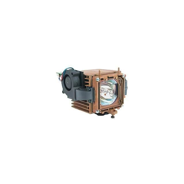
Design Guide for the FOR KNOLL SYSTEMS HD282 Lamp (WW-2L6G-3)
The Interlight WW-2L6G-3 replacement lamp for Knoll Systems HD282 projectors is a small, high-pressure discharge lamp module that makes an excellent teaching vehicle for a ballast-driven illumination design. Because it is a replacement part rather than a bare bulb, you get a defined mechanical envelope and connector, but you still have to respect the electrical characteristics of the arc lamp inside. This tutorial treats it as the load in a practical constant-power driver circuit, with emphasis on the design reasoning that transfers to other HID and arc lamp projects.
Why this component suits a tutorial. The WW-2L6G-3 sits in a category where the lamp cannot be driven directly from a voltage source. Like most projector HID lamps, it needs a high ignition voltage, a current-limited warm-up phase, and then regulated power during steady operation. That gives you three distinct design problems to solve in one project: a strike circuit, a current regulator, and a power control loop. The lamp's compact form factor also means thermal management and wiring layout matter, which are exactly the practical skills a bench tutorial should build.
Design requirements. Work from a target of roughly 100 W delivered to the lamp, which is typical for lamps of this class in small projectors. Set these specifications: input 12 V DC from a bench supply or battery pack, ignition pulse of at least 3 kV, warm-up current limit of about 1.2 A, and steady-state power regulation within plus or minus 5 percent. Add a soft-start ramp of two to three seconds to protect the electrodes, and an open-circuit and arc-failure shutdown. Assume the lamp's steady arc voltage settles somewhere between 70 and 90 V; confirm this with a series current-sense resistor during first light.
Step-by-step design. Start with the boost converter that raises 12 V to a bus of about 120 V. Pick a switching frequency of 100 kHz and size the inductor for continuous conduction at 20 percent load. With a 120 V bus and 1.2 A worst-case current, the inductor sees a peak of about 2 A; a 100 microhenry part rated for 3 A saturation works. The output capacitor should be at least 47 microfarads at 200 V to hold ripple under 2 percent.
Next, design the current regulator. Use a low-side sense resistor of 0.1 ohm and compare its drop against a reference in the feedback amplifier. At 1.2 A the sense voltage is 120 mV, so choose an amplifier with offset under 2 mV. Close the loop with a compensation network giving a crossover near 5 kHz and 60 degrees of phase margin. For the ignition stage, a small flyback or a capacitor-discharge igniter across the lamp terminals generates the 3 kV pulse; keep the igniter isolated from the control loop with a series inductor so the high-voltage transient does not damage the regulator.
Finally, add the power loop. Multiply measured lamp voltage by current in a small analog multiplier or use a microcontroller ADC and a digital PI loop. The PI gains should give a settling time of about 500 ms after warm-up, with the current limit dominating until the arc stabilizes.
BOM rationale. Choose a 100 V, 10 A MOSFET for the boost switch with low gate charge to keep drive losses down. Use a Schottky boost diode rated at 200 V and 3 A; its low forward drop improves efficiency at the 100 W level. The controller can be a standard current-mode PWM IC such as the UC3843 family, which simplifies loop compensation. For the sense amplifier, pick a precision rail-to-rail part. The igniter transformer should be a potted flyback type rated for 4 kV isolation. Use 200 V electrolytics and 250 V film capacitors on the bus, and wire the lamp with silicone-insulated 1 kV cable.
Simulation tips. Model the lamp as a voltage source in series with a resistor during warm-up, then switch to a nonlinear arc model at steady state. Watch the bus voltage overshoot at ignition, the current-limit waveform during warm-up, and the loop response to a 10 percent line step. Check that the igniter pulse does not couple into the sense resistor; if it does, add filtering or improve grounding in the model.
Prototype and testing. Build the boost stage first and verify it into a resistive load before connecting the lamp. Then test the current regulator with a dummy load, and only then add the igniter. Use a differential probe for all lamp measurements and keep hands clear during ignition. Log voltage and current for the first minute of operation and confirm the warm-up ramp matches the simulation.
Verification and optimization. Measure efficiency at 25, 50, and 100 percent load, check thermal rise on the MOSFET and diode, and trim the PI gains if the lamp flickers or hunts. If efficiency falls short, reduce switching losses by lowering frequency slightly or selecting a diode with lower capacitance. Document the final arc voltage and current so the design can be repeated with a spare WW-2L6G-3 lamp.