ADP8863ACBZ-R7 Troubleshooting: Fix IC LED Driver Regulator Issues
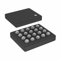
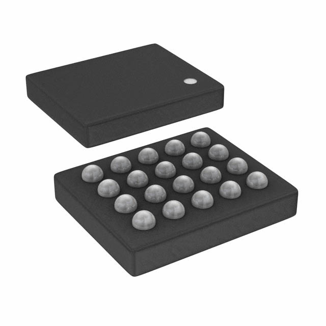
The ADP8863 is a charge-pump-based LED driver with an I2C interface, packaged in a 20-ball WLCSP. In the field, most "dead part" reports turn out to be configuration or layout problems, not silicon failures. The WLCSP package is also easy to damage during rework, so treat every board as suspect until you have measured it.
Typical failure modes and root causes. The most common complaint is "LEDs don't light." Root causes, in order of frequency: the I2C bus never acknowledges (wrong address, missing pull-ups, SDA/SCL swapped), the device is held in shutdown because EN or the software enable bit was never asserted, or the charge pump is current-limited by undersized input capacitors. A second cluster is flicker or dim output: this usually traces to PWM dimming frequency conflicting with the camera frame rate, incorrect dimming register settings, or a noisy VIN rail. A third is thermal shutdown or brownout during all-channels-on transients, which points to layout: long VIN traces, insufficient bulk capacitance, or a ground plane split under the part. Actual silicon failures are rare and usually trace to ESD events during assembly or rework heat damage to the WLCSP balls.
Step-by-step debugging methodology. Start with power: confirm VIN is within the datasheet range and stable, and that the enable pin is at the correct logic level. Next, scope the I2C lines and confirm the device ACKs its address; if not, verify address strapping and pull-up values. Then read back the device registers over I2C if your tooling allows it — a successful readback proves the die is alive and the bus is healthy. After that, enable one LED channel at low current and measure the LED pin voltage and current. Only once basic operation works should you move to dimming modes, fading, and multi-channel sequencing. Keep a known-good reference board for A/B comparison; swapping suspected parts onto a good board is the fastest way to separate component from circuit.
Common schematic and layout mistakes. The classic schematic error is omitting or undersizing the flying and output capacitors for the charge pump; the ADP8863 needs the exact capacitor values and low-ESR parts called out in the datasheet, and substituting a larger value can actually destabilize the pump. Another frequent mistake is tying the I2C address pins incorrectly, or leaving them floating. On layout, the WLCSP's fine-pitch balls demand tight stencil and reflow control; cold joints and bridges are common. Keep the charge-pump capacitors within a few millimeters of the pins with short, wide return paths. Route I2C away from the LED output traces, and do not run LED current returns through the analog ground. Also check that the exposed thermal path, if used, is actually connected — a floating thermal pad causes intermittent thermal shutdown.
Verifying authenticity and quality. Buy only from authorized distributors; the ADP8863 is a popular part and counterfeits exist. Check the marking against the datasheet, verify the date/lot code, and inspect ball uniformity under magnification. On suspect parts, compare I2C ACK behavior and register readback against a known-good unit. X-ray or cross-section is overkill for most field work, but if a batch fails identically at first power-up, quarantine it and contact the distributor. Also check moisture sensitivity level handling — WLCSP parts that absorbed moisture and were reflowed without baking can show cracked die or delamination.
Measurement techniques and equipment. Use a 4-channel scope with a current probe for LED current and a differential probe across the sense resistor. A bench supply with current limiting protects the board during bring-up. For I2C, a logic analyzer or a scope with protocol decode saves hours. Measure VIN at the pin, not at the connector, to catch IR drops. Use a thermal camera or thermocouple to confirm the part stays within ratings during worst-case all-on operation. For current accuracy, a DMM in the LED return path beats inferring from register settings.
Component vs. surrounding circuit. Suspect the component when failures are reproducible across multiple boards with identical symptoms, when the part heats abnormally with no load, or when I2C is completely dead with correct power and pull-ups. Suspect the circuit when behavior changes with layout, when only one board fails, or when symptoms correlate with dimming mode or channel count — those are almost always configuration or power integrity issues.
Real-world case studies. One customer reported random flicker on camera modules; the cause was a dimming frequency beating against the frame rate, fixed by changing the PWM setting, not the part. Another had intermittent shutdown during flash; a scope showed VIN sagging below the UVLO threshold because the bulk capacitor was 10 mm away and the trace was narrow — moving the cap and widening the trace solved it. A third returned "dead" parts that all failed incoming test; reflow profiling showed the WLCSP had been run through a rework station with excessive heat, damaging the balls. A fourth had no I2C ACK because the address pin was left floating on a prototype — a five-minute fix after an hour of part swapping.