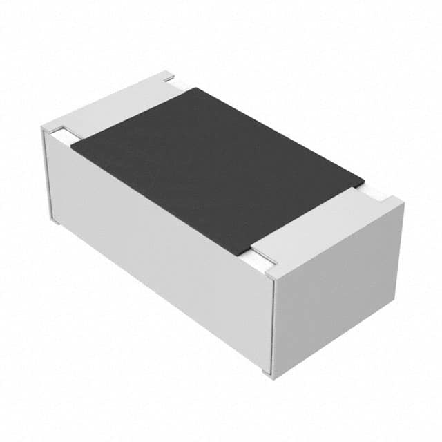
Troubleshooting the ERA-2APB7870X 787-Ohm 0.1% 0402 Resistor
When a design uses the Panasonic ERA-2APB7870X — a 787 Ω, 0.1%, 1/16 W, 0402 thin-film resistor — the tight tolerance and small package both work against you during debug. Most field failures I have seen with this part are not resistor failures at all; they are assembly, layout, or contamination problems that manifest as resistance shifts. This guide reflects what actually happens on the bench.
Typical failure modes and root causes. The dominant failure is a cracked or open solder joint caused by board flexing, connector insertion force, or depanelization stress. 0402 bodies tolerate very little bending, and thin-film elements can crack internally while the solder joints still look perfect. Second is solder wicking onto the termination during reflow, which raises resistance slightly and can open the part under thermal cycling. Third is flux residue or ionic contamination bridging the pads, producing leakage that looks like a low-value resistor on a DMM. Fourth, and rarer, is ESD or transient overstress: this is a 1/16 W part, so a 0402 handling a 12 V transient into a low-impedance node will not survive. Finally, counterfeit or re-reeled parts occasionally appear in broker channels with incorrect marking or tolerance.
Step-by-step debugging methodology. First, confirm the symptom is reproducible and note whether it is thermal (appears after warm-up) or mechanical (changes when the board is flexed). Second, measure the resistor in-circuit with a 4-wire or at least a guarded 2-wire method, and compare against the expected 787 Ω. Third, if the reading is off, lift one pad and re-measure — this separates the part from the surrounding circuit. Fourth, inspect under magnification at 20–40× for cracks, wicking, and residue. Fifth, if the part measures good out of circuit, move to the surrounding nodes: check the op-amp input bias currents, leakage paths, and any capacitors that could be charging through the resistor. Sixth, thermal-cycle the board (e.g., 10 cycles from −40 to +85 °C) and re-measure to catch intermittent cracks.
Common schematic and layout mistakes. Placing this 0.1% part in a divider where the other leg is 1% defeats the purpose entirely — match tolerances across the pair or use a matched network. Routing a sensitive node directly under the resistor body is a classic error: the thin-film element is only microns from the board surface, and coupling from a switching trace beneath it will show up as noise. Using 0402 pads sized for 0603 creates tombstoning and wicking risk. Keepout violations near board edges and V-score lines are the number-one cause of flex cracks. Also check that the power dissipation is genuinely below 1/16 W — in a 787 Ω divider across 5 V, the part dissipates about 8 mW, fine, but across 24 V it is 180 mW and the part will drift or fail.
Verifying authenticity and quality. Buy only from authorized distributors; Panasonic thin-film 0402 parts are frequently counterfeited in gray market. Check the reel label, date code, and that the tolerance marking matches 0.1%. Measure a sample of 20 parts on a calibrated 6.5-digit meter: a genuine batch should cluster near 787 Ω with spread well inside ±0.1%. Out-of-box spread of several ohms indicates relabeled 1% parts. A quick temperature coefficient check (measure at 25 °C and 85 °C) should show under 25 ppm/°C for this series.
Measurement techniques and equipment. Use a 6.5-digit DMM with 4-wire Kelvin clips for any tolerance verification; 2-wire lead resistance alone is enough to swamp a 0.1% measurement. For in-circuit checks, a guarded measurement or a milliohmmeter helps. Use a thermal chamber or hot-air rework station with a thermocouple for drift testing, and a stereo microscope at 20–40× for inspection. An LCR meter at 1 kHz confirms the part is resistive, not a capacitor or inductor misloaded.
When to suspect the component vs. the circuit. Suspect the resistor if the failure is isolated to one board, appears after mechanical stress, or the value drifts with temperature beyond spec. Suspect the circuit if multiple boards fail identically, if the node is near a switching supply, or if the measured error tracks a change in a neighboring component. Never replace the part before lifting a pad and measuring it.
Real-world case studies. A customer reported a 0.3% gain error in an instrumentation amplifier; the 787 Ω feedback resistor measured 789 Ω in-circuit. Lifting the pad showed 787.0 Ω — the error was leakage from a contaminated no-clean flux residue across the adjacent pads, fixed by cleaning and adjusting the reflow profile. Another case: intermittent failures after board depanelization traced to V-score lines routed within 0.5 mm of the resistor pads; moving the part 2 mm from the edge eliminated the cracks. A third: a batch from a broker measured 781–794 Ω out of the bag — relabeled 1% parts — caught only by sampling 20 pieces on a calibrated meter.
RES SMD 787 OHM 0.1% 1/16W 0402
Panasonic Electronic Components | ERA-2APB7870X | $0.76