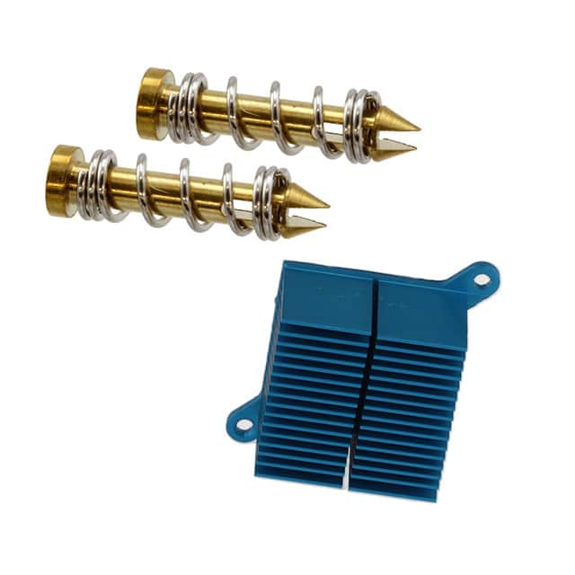
HEATSINK 30X30X25MM R-TAB T766 Application Note: Thermal Design Guide
The ATS-18F-172-C2-R0 (HEATSINK 30X30X25MM R-TAB T766) from Advanced Thermal Solutions Inc. is a passive, radial-fin extrusion measuring 30 mm by 30 mm with a 25 mm profile height, and it is not a circuit-level component in the usual sense. Instead, it is a thermal management device intended for forced- or natural-convection cooling of surface-mount power devices such as TO-220/TO-247-style regulators, MOSFETs, IGBTs, and diode packages. Because the part is passive and non-electrical, the "topologies" that matter are thermal topologies: choose between natural convection (no airflow, relying on fin orientation and buoyancy), forced convection (fan-driven airflow across the fin stack), and conduction-based mounting (directly coupling the heatsink base to a copper pad or chassis). For most designs, a forced-convection arrangement with airflow directed along the fin channels yields the highest thermal performance per unit volume. The R-tab mounting feature allows a screw or clip attachment to a device tab, which is convenient for through-hole and TO-style packages. Best practice is to keep the heatsink's thermal path short and direct: place the heatsink as close to the heat source as possible, use a thin, uniform layer of thermal interface material, and avoid stacking interfaces unless the mechanical design requires isolation.
Supporting passives are selected to complement the thermal and electrical behavior of the power stage rather than the heatsink itself. Use low-ESR electrolytic or ceramic input and output capacitors rated for the ripple current and temperature rise that the power device will see; derate capacitor voltage and temperature ratings generously because the heatsink raises local ambient temperatures. For gate-drive and bias networks, choose resistors and capacitors with temperature coefficients appropriate to the elevated local ambient near the heatsink, typically 105 °C or 125 °C rated parts. If the heatsink is electrically isolated from the device tab, verify that the isolation pad or thermal interface material meets the required dielectric withstand voltage. Snubber and clamp components should be sized for the switching node's dv/dt and di/dt, not merely for steady-state values, since the heatsink's presence can change parasitic capacitance to the surrounding enclosure.
PCB layout should treat the heatsink as a mechanical and thermal element first. Provide a generous copper pour under and around the power device to spread heat into the board, and use thermal vias to connect to inner copper layers where appropriate. Keep the heatsink footprint free of tall components and traces that could be damaged during assembly or by vibration. Route high-current paths with short, wide traces and keep the switching loop small to minimize radiated emissions. When the heatsink is mounted with a screw or clip, ensure the mounting hardware does not short to nearby traces, and provide clearance for the R-tab and any clip fingers. If the heatsink is grounded or floating, document that clearly in the assembly drawing. Orient the fins to align with the intended airflow direction; a 90-degree misorientation can significantly reduce convection efficiency.
From an EMC/EMI perspective, the heatsink is a conductor and can act as an antenna or as a capacitive coupling path to the switching node. If the device tab is electrically connected to a switching node, the heatsink will carry that switching voltage and should be tied to a stable potential (typically ground or a quiet rail) through a low-impedance connection, or isolated with a suitable thermal interface pad. Avoid leaving a floating heatsink near high-dv/dt nodes, as this can create unpredictable common-mode currents. Keep the heatsink away from sensitive analog or RF traces, and where proximity is unavoidable, use a grounded shield or a grounded copper pour between the heatsink and the sensitive circuitry. Verify emissions with the heatsink installed, since bench measurements without the heatsink can understate radiated emissions.
Common pitfalls include using excessive thermal interface material, which increases thermal resistance rather than reducing it; over-tightening mounting hardware and cracking the device or the heatsink base; and ignoring airflow direction. Another frequent error is assuming the heatsink's rated thermal resistance applies in the actual enclosure; that figure is typically measured under specific conditions and must be derated for confined spaces and elevated ambient. Designers also sometimes forget that the heatsink adds height and mass, which affects shock and vibration performance and can interfere with enclosure lids. Finally, be careful not to route traces beneath the heatsink footprint where they can be abraded or shorted by mounting hardware.
For prototyping, mount the heatsink and device on a representative board and measure the device case temperature with a thermocouple under worst-case load and ambient conditions. Use a thermal camera or thermocouple array to map the heatsink base and fin temperatures, and compare against the datasheet thermal resistance to confirm the design margin. Run the system at maximum continuous power for sufficient time to reach thermal steady state, then repeat with the enclosure installed. Perform conducted and radiated emissions scans with the heatsink in place, and check for hot spots near the mounting hardware. A simple bench test with a variable-speed fan can help characterize the natural-convection and forced-convection operating points before committing to production airflow assumptions.
HEATSINK 30X30X25MM R-TAB T766
Advanced Thermal Solutions Inc. | ATS-18F-172-C2-R0 | $6.18