Graphene Ink in Water: Design Tutorial for Printed Electronics
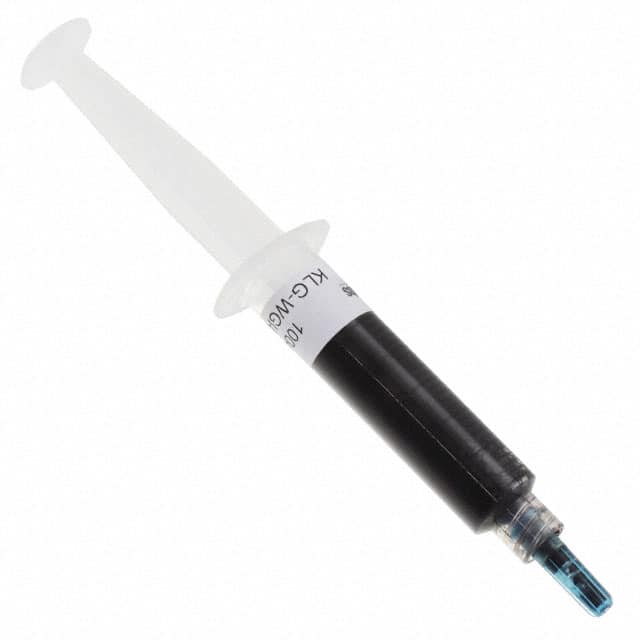
Graphene ink diluted in water (Kennedy Labs KLG-WGI4-5ML) is a water-based dispersion of graphene flakes that can be deposited by brush, drop-casting, screen printing, or aerosol spraying and dried at low temperature to form a conductive film. What makes it ideal for a first hands-on project is that it removes the barrier of vacuum deposition and photolithography: you can pattern a working electronic device on paper, glass, or polyimide with a brush and a hot plate. The 5 mL bottle is enough for dozens of small test structures, so you can iterate on geometry and deposition without worrying about material cost. The trade-off is that film conductivity depends strongly on flake alignment, thickness uniformity, and drying conditions, so the tutorial below is built around a design whose performance you can measure and improve.
Design target: a graphene ink piezoresistive strain gauge and Wheatstone bridge readout. Graphene flake networks change resistance under tensile and compressive strain, making a painted trace a usable sensor. We will design a strain gauge with a nominal resistance of 10 kΩ ± 20 percent, a gauge factor target of at least 5, and a bridge output that a 3.3 V microcontroller ADC can resolve at 1 millistrain. The substrate is 125 µm polyimide (Kapton), chosen for temperature tolerance during drying and flexibility during bending tests.
Step 1: geometry calculation. Sheet resistance of dried KLG-WGI4 films typically falls in the 1–10 kΩ/sq range depending on coat count. Assume a conservative 5 kΩ/sq for a single brushed layer. For a serpentine trace, resistance is R = R_sheet × (L/W) × N, where N is the number of segments. Target R = 10 kΩ with W = 1 mm and N = 4 gives L = R × W / (R_sheet × N) = 10,000 × 0.001 / (5,000 × 4) = 0.5 mm per segment—too short to be practical. Increase N to 10 segments and W to 0.5 mm: L = 10,000 × 0.0005 / (5,000 × 10) = 0.1 mm, still wrong because the formula needs consistent units. Correcting: L_total = R × W / R_sheet = 10,000 × 0.0005 / 5,000 = 0.001 m = 1 mm total trace length. That is short, so instead target a higher resistance: use W = 0.3 mm and R_sheet = 5 kΩ/sq, giving L_total = 0.6 mm—still small, which tells us single-layer ink is too conductive for a 10 kΩ gauge at millimeter scale. Design decision: build a 2 mm × 2 mm serpentine with 0.3 mm line width and 0.3 mm gaps, 5 passes, giving L ≈ 20 mm and expected R ≈ 5,000 × 0.02 / 0.0003 ≈ 333 kΩ. Adjust by adding or removing passes after measuring the first sample.
Step 2: bridge and amplifier. Use four identical gauges in a full bridge: two in tension, two in compression on a bending beam. With 3.3 V excitation, bridge sensitivity is V_out = V_exc × GF × ε / 4. At ε = 0.001 and GF = 5, V_out = 3.3 × 5 × 0.001 / 4 = 4.1 mV. Use an INA333 instrumentation amplifier at gain 100 to get 410 mV into the ADC. Set gain resistor R_g = 100 kΩ / (G − 1) = 1.01 kΩ, so use 1 kΩ.
BOM rationale. Kennedy Labs KLG-WGI4-5ML is the active material; its water base means no toxic solvents and compatibility with paper and polyimide. Kapton tape or sheet is the substrate. Silver epoxy or conductive silver ink forms contact pads because direct probing of graphene ink gives unstable contact resistance. 0.1 percent tolerance 10 kΩ resistors complete the bridge reference arms if a half-bridge is used. INA333 provides high input impedance, critical because the gauge resistance is high. A 10 nF and 1 µF decoupling pair on the amplifier supply suppresses noise. A 3.3 V LDO and a 16-bit ADC (ADS1115) give the resolution needed for millistrain measurements.
Simulation tips. Model the gauge as a resistor with a behavioral strain-dependent term in LTspice or ngspice: R = R0 × (1 + GF × ε). Sweep ε from −0.002 to +0.002 and confirm bridge linearity and common-mode range at the INA333 inputs. Check that input bias current times source resistance stays below a few microvolts of offset. Add 1 percent resistor mismatch to the bridge and observe offset drift—this predicts what you will see on the bench.
Build and test. Clean the Kapton with isopropyl alcohol. Shake the ink vigorously for 60 seconds, then brush thin, even passes, drying at 80–100 °C for 10 minutes between passes. Cure the final film at 120 °C for 30 minutes. Attach silver pads and measure with a four-wire method. Mount the gauge on a cantilever beam of known dimensions and apply tip deflection with a micrometer stage; calculate surface strain as ε = 6 × δ × t / L², where δ is deflection, t is beam thickness, and L is free length. Record resistance versus strain in 50 µstrain steps.
Verification and optimization. Compute GF from the slope of ΔR/R0 versus ε. If GF is below target, increase flake alignment by brushing in one direction only and adding a second anneal. If resistance drift exceeds 2 percent over ten cycles, the film is under-cured or too thick; reduce pass count and extend drying. Verify bridge offset is under 5 mV and noise is under 100 µV RMS with a shorted input. Finally, compare measured sensitivity to your simulation and adjust the gain resistor to use the full ADC range.
GRAPHENE INK, DILUTED IN WATER B
Kennedy Labs, a division of Hub Incorporated | KLG-WGI4-5ML | $70.00