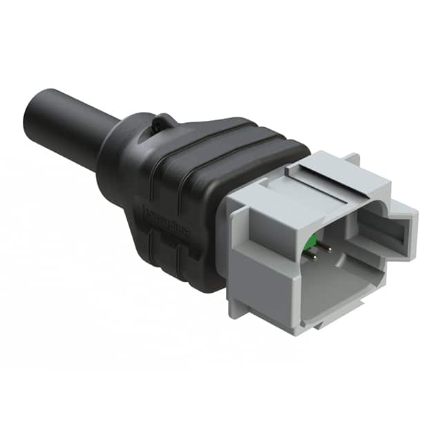
8-Pin Single-End Receptacle AT04GY-08PA: Application Note
The Amphenol Sine Systems AT04GY-08PA-N-TPE-M4 is an 8-position, single-ended receptacle designed for robust, environmentally sealed connections in industrial, automotive, and harsh-environment applications. This application note provides practical guidance for integrating this connector into your design, focusing on circuit topologies, supporting components, PCB layout, EMC/EMI, common pitfalls, and prototyping procedures.
Recommended Circuit Topologies and Design Best Practices
For single-ended signaling through this receptacle, the most common topology is a point-to-point connection between a driver and a receiver, with a shared ground return. Each of the eight contacts can carry a digital signal, analog signal, or power. For digital signals, use a series termination resistor placed as close as possible to the driving source (e.g., microcontroller or FPGA output pin) to match the characteristic impedance of the cable and connector system. Typical values range from 22 to 50 ohms, but you must determine the exact value based on the cable’s impedance and the driver’s output impedance. For analog signals, especially low-level ones, use differential pairs to reduce noise pickup, even though the connector is single-ended. This means dedicating two contacts per signal (one for signal, one for return) and routing them as a pair on the PCB. For power delivery, ensure each power contact can handle the rated current (typically 13A per contact for this series) and use multiple contacts in parallel for higher current, distributing the load evenly. Always include a dedicated ground return contact for every two to three signal contacts to minimize ground loops and reduce impedance.
Component Selection Guidelines for Supporting Passives
Selecting the correct supporting components is critical for reliable operation. For ESD protection, use TVS diodes with a breakdown voltage slightly above the maximum signal voltage (e.g., 5V for 3.3V logic) and low clamping voltage. Place these diodes directly at the connector pins on the PCB. For series termination resistors, choose surface-mount resistors in 0402 or 0603 packages with low inductance (typically thick film) and ensure their power rating exceeds the peak power dissipation from signal transitions. For decoupling, use a combination of bulk capacitors (e.g., 10 µF to 100 µF, aluminum electrolytic or tantalum) and high-frequency ceramic capacitors (0.1 µF and 0.01 µF) near each power pin of the connector. The ceramic capacitors should be X7R or C0G dielectric for stable capacitance over temperature and voltage. For filtering noisy signals, consider ferrite beads with an impedance of 100-600 ohms at 100 MHz, placed in series with the signal line, but only if signal integrity allows (avoid for high-speed signals above 10 MHz).
PCB Layout Recommendations and Routing Tips
PCB layout directly impacts signal integrity and reliability. Place the connector near the edge of the board to minimize cable strain and facilitate mating. Use a solid ground plane on the layer immediately below the connector’s footprint to provide a low-impedance return path. For each signal contact, route the trace as a controlled impedance line (e.g., 50 ohms for microstrip or stripline) if the signal frequency exceeds 50 MHz. Ensure trace widths and spacing are consistent with the PCB stackup. For analog signals, keep traces short (under 100 mm) and avoid routing them near high-speed digital lines or switching power supplies. Use ground guard traces around sensitive analog lines, with vias stitching the guard to the ground plane every 5-10 mm. For power contacts, use wide traces (at least 2 mm per amp) or copper pours to minimize voltage drop and heating. Avoid acute angles in traces; use 45-degree corners or curved traces. Finally, assign a dedicated ground pin on the connector to the PCB ground plane with multiple vias (at least two per pin) to reduce inductance.
EMC/EMI Considerations and Mitigation Strategies
The single-ended nature of this connector makes it susceptible to common-mode noise, which can radiate or couple into other circuits. To mitigate EMI, use a shielded cable with the shield connected to the PCB ground at the connector end only (to avoid ground loops). If the receptacle has a metal shell, ensure it is connected to chassis ground through a low-impedance path, such as a dedicated mounting screw or a wide copper trace with multiple vias. For signals, add common-mode choke filters (e.g., CMFC series) on the cable side if the system must pass strict emissions standards. On the PCB, use a ferrite bead or a 100-ohm resistor in series with the ground connection between the connector and the main ground plane to suppress high-frequency noise, but only if the ground is not used for safety. Implement a pi-filter (series ferrite bead, shunt capacitor to ground) on each power line entering the connector. Keep all filter components as close to the connector pins as possible, with short traces to minimize loop area. Finally, avoid routing sensitive traces under the connector on inner layers, as the connector’s plastic body can create parasitic capacitance.
Common Design Pitfalls and How to Avoid Them
One frequent mistake is assuming all contacts are identical in performance. In reality, contact resistance can vary due to insertion cycles and environmental contamination. Always design with a margin of at least 20% on voltage and current ratings. Another pitfall is inadequate strain relief for the cable, which can cause intermittent connections or pin damage. Use the manufacturer’s recommended backshell or cable clamp and ensure the cable jacket is secured, not just the individual wires. Overlooking the connector’s IP rating (typically IP67 for this series) is also common; if your application requires a seal, verify that the mating plug and the receptacle are properly mated and that any unused contacts are sealed with dummy plugs. Failing to account for the connector’s inductance (approximately 5-10 nH per contact) can cause ringing on high-speed signals; add a series resistor or use a slower edge rate to dampen oscillations. Lastly, don’t ignore the operating temperature range (-40°C to +125°C); use components rated for the full range, especially capacitors and resistors, to avoid failures in thermal cycling.
Prototyping Tips and Bench Testing Procedures
When prototyping, start with a simple breakout board that replicates the final PCB footprint. Solder wires to the connector contacts using a low-temperature solder (e.g., Sn63Pb37) to avoid damaging the plastic housing. For initial testing, use a multimeter to check continuity and verify that no adjacent pins are shorted (common due to solder bridges). Then, apply a low-frequency square wave (1 kHz, 50% duty cycle) from a function generator to one contact while monitoring the output with an oscilloscope. Check for signal degradation like rise-time slowdown or overshoot. For power testing, apply a load current up to the rated value and measure the voltage drop across the connector using a four-wire Kelvin measurement. Use a thermal camera to identify hot spots on the PCB or connector. For EMC pre-compliance, use a near-field probe connected to a spectrum analyzer to scan the connector area for emissions at the system clock frequency and its harmonics. Finally, perform a mating cycle test (at least 50 insertions) to ensure contact resistance remains stable. Document all measurements and adjust your design accordingly before moving to production.
8 POSITION RECEPTACLE SINGLE-END
Amphenol Sine Systems Corp | AT04GY-08PA-N-TPE-M4 | $45.43