Troubleshooting Miniature 10V .014A (10PAK): Key Fixes
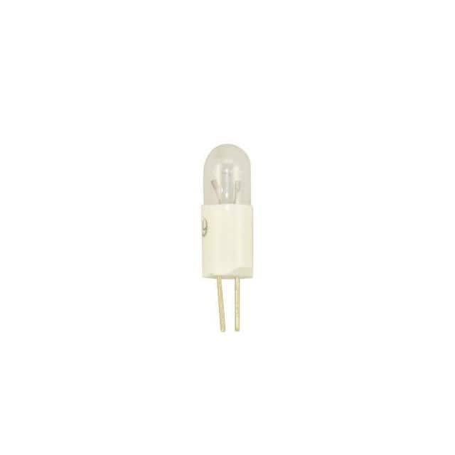
When working with the Interlight miniature 10V, 0.014A (14mA) component, often used in indicator lamps or low-power signal circuits, field issues typically fall into a predictable set of failure modes. The most common is a complete open circuit, where the filament or internal bond wire has fractured. This is usually caused by mechanical stress from excessive board flex, thermal shock from soldering, or inrush current exceeding the low 14mA rating. Another frequent failure is a gradual dimming or intermittent operation, which often points to a poor solder joint or a cracked solder connection at the component leads. Less common but still problematic is a short circuit, which can occur if the miniature package is crushed or if conductive debris bridges the terminals. A third failure mode is a shift in brightness or voltage drop, often a sign of internal degradation due to prolonged operation near the absolute maximum rating of 10V.
To debug these issues, follow a systematic, step-by-step methodology. Step one: Visual Inspection. Use a 10x to 40x stereo microscope. Look for cracks in the glass envelope, discoloration of the internal filament, or any loose metal particles. Check the solder joints for cold solder, insufficient wetting, or cracks at the lead-to-solder interface. Step two: Power-off Resistance Check. Using a digital multimeter (DMM) set to resistance mode, measure across the component terminals. A good component should show a low resistance, typically in the range of 700 to 900 ohms. An open circuit (OL) indicates a broken filament. A reading of near zero ohms suggests a short. Step three: Power-on Voltage and Current Measurement. Apply power and measure the voltage directly across the component terminals with your DMM. If the voltage is 10V but the component is not lit, the internal filament is open. If the voltage is significantly lower (e.g., 2V) and the component is dim, you may have a high-resistance connection or the component is being current-limited by another part of the circuit. Measure the current in series with the component. At 10V, it should be approximately 14mA. A current reading of zero confirms an open circuit, while a much higher current (e.g., over 20mA) indicates a short or a problem with the current-limiting resistor.
Common mistakes in schematic design and PCB layout are the primary drivers of field failures. In schematics, the most critical error is failing to include a current-limiting resistor. This miniature component is not designed for direct connection to a 10V supply without a series resistor to set the 14mA current. Many engineers mistakenly assume the component has internal current regulation. Always calculate the resistor value using Ohm’s Law: (Supply Voltage - 10V) / 0.014A. For a 12V supply, this would be (12-10)/0.014 = 142 ohms, so use a 150-ohm standard value. In PCB layout, the biggest mistake is placing the component too close to heat-generating elements like voltage regulators or power resistors. The miniature package’s glass-to-metal seal is susceptible to thermal stress, leading to eventual cracking. Another common error is routing high-current traces or noisy switching signals directly under or adjacent to the component’s pins, which can induce voltage spikes that exceed the 10V rating. Ensure at least 5mm of clearance from high-power components.
Verifying component authenticity and quality is crucial, as counterfeit or substandard parts are a real concern. The Interlight brand is generally reliable, but always purchase from authorized distributors. When suspecting a counterfeit, first check the physical markings. Authentic Interlight parts typically have a clear, laser-etched part number and voltage/current rating on the body. Counterfeits may have smudged, painted, or missing markings. Second, weigh the component on a precision scale. The genuine part has a consistent weight due to specific materials. Third, perform a simple electrical test: measure the cold resistance. A genuine part should fall within a narrow tolerance (e.g., 800 ohms ±10%). A counterfeit might measure 500 ohms or 1.2k ohms. Finally, subject a sample to a thermal cycle test (e.g., -20°C to +85°C for 10 cycles) and verify it still functions. Counterfeits often fail this test due to inferior internal construction.
For measurement techniques, you will need a few key pieces of test equipment. A good-quality digital multimeter (DMM) with a 0.1mV resolution is essential for precise voltage and resistance measurements. An oscilloscope with at least 20MHz bandwidth is critical for catching transient overvoltage spikes that a DMM will miss. Use a differential probe or a ground-reference probe with a short ground spring to avoid noise. When measuring current, use the DMM in series, but be aware of the voltage burden (typically 0.1V to 0.2V) which can slightly reduce the voltage across the component. For a more accurate current measurement, use a precision current shunt resistor (e.g., 10 ohms, 1%) in series and measure the voltage drop across it with the oscilloscope.
Knowing when to suspect the component versus the surrounding circuit is a key skill. Suspect the component first if the failure is isolated to one unit in a batch of otherwise working boards, and if visual inspection shows clear physical damage. If you see multiple failures on different boards, especially in the same location, the likelihood shifts to a circuit design or layout issue. A classic real-world case involved a customer with intermittent failures of this component in a temperature controller. The DMM showed a steady 10V, but an oscilloscope revealed a 15V, 100µs spike during power-up caused by a slow-start capacitor in the 12V supply being too small. Replacing the component did not fix the problem; adding a larger 100µF capacitor and a series 150-ohm resistor did. Another case involved a batch of parts that all failed within a week. Visual inspection showed no damage, but resistance measurements were erratic. The root cause was a counterfeit batch with internal wire bonds that were too thin. Replacing all components from an authorized distributor solved the issue.
Finally, always consider the operating environment. If the circuit is in a high-vibration environment, such as near a motor or pump, the miniature component’s fragile filament can fail mechanically. Adding a small series resistor (even 10 ohms) to limit current during vibration-induced contact bounce can dramatically improve reliability. In summary, systematic measurement, careful layout, and a healthy skepticism toward component authenticity are your best tools for debugging this specific miniature 10V, 14mA component.