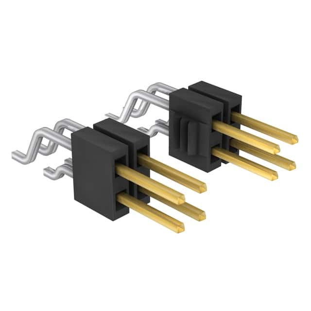
30-Pin 1.27mm SMD Right-Angle Header: Reliability Guide
This reliability and quality guide addresses the Samtec FTSH-115-02-F-DH, a 30-position, 1.27mm pitch, right-angle, surface-mount (SMD) header. As a high-density interconnect, its performance is critical in professional electronics, particularly in applications like industrial control, medical devices, and communications equipment where vibration and thermal cycling are common. The following sections detail the essential considerations for ensuring its long-term reliability and quality in your supply chain.
Reliability Standards and Qualifications
The FTSH series from Samtec is typically manufactured under an ISO 9001:2015 certified quality management system. For reliability testing, Samtec often adheres to industry standards such as EIA-364 for electrical connectors. Key qualifications for this header include mechanical shock (EIA-364-27), vibration (EIA-364-28), and thermal shock (EIA-364-32). The component is designed for a minimum of 100 mating cycles, and its gold-plated contacts (0.10µm gold over nickel on the mating interface) provide excellent corrosion resistance. The "F" suffix in the part number indicates a 10µ" (0.25µm) gold plating on the tail, which is sufficient for soldering but not for repeated mating. Always verify the manufacturer's qualification test report (QTR) for specific test conditions, such as temperature range (-55°C to +125°C) and humidity exposure (e.g., 85°C/85% RH).
Accelerated Life Testing and What the Results Mean
Accelerated life testing (ALT) for this connector often involves temperature cycling (e.g., -55°C to +125°C for 500 cycles) and damp heat testing (e.g., 85°C/85% RH for 1000 hours). These tests stress the solder joints, contact interface, and plastic housing. Results are typically expressed as a change in contact resistance; a threshold of less than 5mΩ change is a common acceptance criterion. For example, a test with 500 thermal cycles might show a median resistance shift of only 0.5mΩ, indicating robust reliability. The acceleration factor, often derived from the Arrhenius model, allows you to extrapolate these test results to real-world operating conditions. If the component passes 1000 hours at 125°C, it may correspond to over 10 years of operation at 65°C, assuming a typical activation energy of 0.7 eV. However, be aware that mechanical stresses from thermal expansion mismatch (between the header's liquid crystal polymer housing and the PCB) can dominate failure mechanisms, so temperature cycling data is particularly valuable.
Failure Rate Calculations (FIT Rates) and MTBF Considerations
For this SMD header, failure rates are often reported in FITs (Failures In Time, per 10^9 device-hours). A typical FIT rate for a well-qualified Samtec header in a controlled environment might be in the range of 1 to 10 FITs per contact. For a 30-position header, the system-level FIT is approximately 30 to 300 FITs, assuming independent failure rates. This translates to a Mean Time Between Failures (MTBF) of roughly 380,000 to 3.8 million hours. These calculations assume a constant failure rate during the useful life period, which is valid after the infant mortality phase. The primary failure modes are contact fretting corrosion (accelerated by vibration and thermal cycling) and solder joint fatigue. When using these numbers, apply a reliability prediction standard like MIL-HDBK-217 or Telcordia SR-332, but note that connector failures are often mechanical rather than purely electrical, so empirical data from ALT is more accurate. Samtec typically provides FIT data upon request for specific applications.
Environmental Stress Screening and Burn-In Procedures
Environmental stress screening (ESS) for commercial-grade headers like this is not always standard, but it can be justified for high-reliability applications. A typical burn-in procedure might involve a 168-hour temperature cycle from -40°C to +85°C with a 30-minute dwell time. During this process, the connector should be mated with its counterpart (e.g., a Samtec FFSD series IDC cable) to verify contact integrity. Continuous monitoring of contact resistance is recommended; a 10mΩ increase is a common failure threshold. Vibration screening (e.g., 20g random for 30 minutes) can also be applied to dislodge poorly seated contacts. However, be cautious: excessive burn-in can degrade the plastic housing or induce stress relaxation in the beryllium copper contacts. For most professional applications, a shorter, 24-hour thermal cycle is sufficient to identify infant mortality without reducing the component's useful life.
Counterfeit Detection Methods Specific to This Component Type
Given the FTSH series' popularity, counterfeiting is a risk, particularly with high-value, fine-pitch headers. Key detection methods include visual inspection under a microscope (10x-40x magnification). Authentic Samtec parts have a precisely molded, "LCP" (Liquid Crystal Polymer) housing with smooth, flash-free edges and a consistent dark gray or black color. The gold plating should be bright and uniform; counterfeit parts often show dull, uneven plating or pitting. Check the RoHS and date code markings; genuine Samtec headers have laser-etched or ink-marked codes that are sharp and aligned. Dimensional verification is critical: measure the pitch (1.27mm center-to-center), the board standoff height (typically 3.05mm for the FTSH-115), and the tail length. X-ray fluorescence (XRF) analysis can verify gold thickness (10µ" minimum on the tail). Finally, a simple thermal test—heating the component to 260°C for 10 seconds—can reveal counterfeit LCP that may warp or discolor. Always source from authorized distributors like DigiKey or Mouser to mitigate counterfeit risk.
Incoming Inspection Best Practices
Upon receipt, perform the following checks. Visual inspection: Examine for bent or missing pins, solder wicking up the tails, or damage to the plastic housing. Use a 10x microscope for all 30 positions. Dimensional verification: Measure the overall length (approximately 39.37mm for a 30-position header), the right-angle standoff, and the pin coplanarity (should be within 0.10mm). Electrical continuity: Use a multimeter to verify that all pins are electrically isolated from each other and that no shorts exist between adjacent contacts. Contact resistance: Mate the header with a known good counterpart (e.g., a Samtec FFSD-115-IDC cable) and measure the daisy-chain resistance; a typical specification is < 15mΩ per contact. Solderability test: Dip a sample tail in flux and then in molten solder (245°C for 3 seconds); the solder should wet the tail uniformly without dewetting. Document all results for traceability.
Storage and Handling Requirements to Maintain Reliability
This component is moisture-sensitive, though it is typically classified as MSL 1 (Moisture Sensitivity Level) due to the LCP housing, meaning no special baking is required before soldering if stored properly. However, to prevent oxidation of the gold-plated contacts, store in a clean, dry environment with a temperature between 15°C and 25°C and relative humidity below 60%. Use anti-static bags or trays to avoid electrostatic discharge (ESD) damage, as the contacts are not ESD-sensitive but the packaging can accumulate charge. Avoid storing in areas with corrosive gases (e.g., sulfur, chlorine) which can tarnish the gold. For long-term storage (over 12 months), consider vacuum-sealing with desiccant. When handling, use tweezers or a vacuum pick-up tool to avoid bending the leads. Never touch the mating surface of the contacts with bare fingers, as skin oils can degrade the contact interface and accelerate fretting corrosion.
End-of-Life Management and Obsolescence Planning
Samtec has a strong reputation for product longevity, but the FTSH series could eventually face obsolescence. To manage this, maintain a 12-month rolling forecast and stock a minimum of 6 to 12 months of demand for critical applications. Identify potential drop-in replacements, such as the FTSH-115-02-L-DH (with a different plating option) or the TSM-115-02-T-DH (with tin plating). When planning for end-of-life, consider redesigning with a compatible, newer Samtec series like the FTSH-115-02-F-DH-A (with alignment pins) or a different pitch. Establish a relationship with Samtec's customer service to get early obsolescence notifications. For legacy systems, consider a last-time buy with a 2- to 5-year inventory buffer. Store this inventory in a controlled environment and periodically test samples for solderability and contact resistance every 2 years. By implementing these strategies, you can mitigate the risk of supply chain disruptions and maintain system reliability over the product's lifecycle.